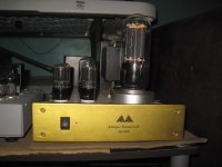
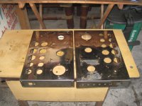
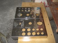
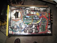
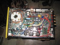
completed repair on another pair Antique sounds 1006 SET power amp..repairs done were to replace the OPT's with manufacturer spares, then dc filament supplies to the 6sn7 tubes replaced with a beefier type bridge rectifiers...
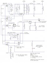
to those interested, this amp is a single ended amp capable of at least 20 watts of output power....power dram from meralco is around 170 watts...
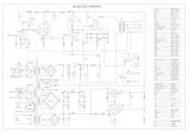
topology of this amp is like these: 6SN7 srpp voltage amp input stage, buffered by a paralleled section 6SN7 cathode follower feeding another 6SN7 active loaded voltage amp that feed the 845 grid, the 845 is fixed bias at around 80mA for an idle dissipation of around 80 watts...
you might be wondering what the 6L6gwb and the 6sl7 tubes are doing there, well, they are a voltage regulators that supplied low impedance power to the 3 6SN7's...the 6L6gwb is the series pass element and the 6sl7 tube is the error amplifier using a zener voltage reference at its cathodes..
in the course of repairing this amps, i found out that there were 3 coupling caps in the signal path, compared to the original published schematics with only two, so i investigated and found out that the second stage cathode follower were converted to cascaded cathode follower to justify a third cap....i have never seen such a practice before and can not see any logic behind it, so i simply restored the amp to its original configuration....done away with one cap and a power resistor...
imho, the 2nd stage 6sn7 cathode followers can be taken out altogether i do not see any compelling reason for putting it there except to say that Antique sounds might have truckloads of 6sn7's....but hey, this is not my amp so i will just let it be...
sorry for the long post....")
to those interested, this amp is a single ended amp capable of at least 20 watts of output power....power dram from meralco is around 170 watts...
topology of this amp is like these: 6SN7 srpp voltage amp input stage, buffered by a paralleled section 6SN7 cathode follower feeding another 6SN7 active loaded voltage amp that feed the 845 grid, the 845 is fixed bias at around 80mA for an idle dissipation of around 80 watts...
you might be wondering what the 6L6gwb and the 6sl7 tubes are doing there, well, they are a voltage regulators that supplied low impedance power to the 3 6SN7's...the 6L6gwb is the series pass element and the 6sl7 tube is the error amplifier using a zener voltage reference at its cathodes..
in the course of repairing this amps, i found out that there were 3 coupling caps in the signal path, compared to the original published schematics with only two, so i investigated and found out that the second stage cathode follower were converted to cascaded cathode follower to justify a third cap....i have never seen such a practice before and can not see any logic behind it, so i simply restored the amp to its original configuration....done away with one cap and a power resistor...
imho, the 2nd stage 6sn7 cathode followers can be taken out altogether i do not see any compelling reason for putting it there except to say that Antique sounds might have truckloads of 6sn7's....but hey, this is not my amp so i will just let it be...
sorry for the long post....
Attachments
one thing i noticed with ASL is their penchant to use the 6SN7..
i have another pair that i have stripped down to bare metal chassis
that i intend to rebuild....
i will rebuild with just one voltage amp gain stage and cathode followers
making it a three tube amp...
i am making the psu to use 3 470/450v ecaps in series so that they
are safe in the long term...
i have another pair that i have stripped down to bare metal chassis
that i intend to rebuild....
i will rebuild with just one voltage amp gain stage and cathode followers
making it a three tube amp...
i am making the psu to use 3 470/450v ecaps in series so that they
are safe in the long term...
Sounds like a fun project. I think the fact that the 6SN7 has moderate mu and rp plus really stellar linearity accounts for its popularity. Oddly the fact that it's "big" might have something to do with the mystique.
I have had some problems with stacking 3 large electrolytics in series with even with hefty voltage equalization resistors. I'd probably consider 5W wire wounds and at least 5mA of current through the resistors. A large short term overload margin (pulse rated) might help.
I had quite a few caps and resistors that had failed or were failing in the HV supply of my GM70 amps in just 5 yrs. I was very surprised.
yes, the mu of the 6SN7 necessitates using cascaded stages...
to me, i will just get a tube with desired gain...
i am looking at a no global feedback build if i can get away with it...
i wish they made ecaps with 750 volts working voltage....
i am using the 6SL7 and 6BX7 in my redesign and rebuild...
i have seen failure in the dc psu feeding the 3 6sn7 filaments,
the filter cap fried, the bridge rectifier failed as a open circuit...
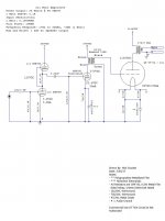
i am redesigning the power traffo, there will be three tier power supply similar to the one used here...Champ 1000 Watt Tube Amp
Champ CBA-1000 Amplifier - Schematic Diagram
my reasoning is that it is easier to build traffos with several lower voltage secondaries than a single 780vac winding used here....
also, the same psu can use to power the lower voltage input and driver stages
by tapping into this psu...
Champ CBA-1000 Amplifier - Schematic Diagram
my reasoning is that it is easier to build traffos with several lower voltage secondaries than a single 780vac winding used here....
also, the same psu can use to power the lower voltage input and driver stages
by tapping into this psu...
Is this the schematic?
I have a CD that I downloaded a lot of the schematics for Antique Sounds a few years back.
yes, i am ditching the 2nd 6sn7 cathode follower, i see no real purpose for that to be in there..
i am also splitting the ac into three instead of just one winding...
that means a redesign and rebuild of the power traffos...
i am also splitting the ac into three instead of just one winding...
There are multiple secondaries on that power supply transformer
A good approach is a separate filament and high voltage transformer because high voltage rectification is solid state.
The negative supply for the output stage also coming from that filament transformer.
The high voltage dc for the output stage controlled by a relay which can be powered by the negative grid supply.
This way you have a better start up of the amplifier, and safety for the output tubes in case of negative grid supply failure.
Output tube filament/cathode supply can be much improved by using a CCS instead of simply rectified DC.
Last edited:
i am using the 6SL7 and 6BX7 in my redesign and rebuild...
I recently rebuilt the driver circuit in my 211 mono amps using a 6SN7 SRPP / 6BX7GT and Hammond 126B. I am now getting 25 Watts output at 5% THD.
When I originally designed these amps back in 2000, I was on a budget, so I used a 6SL7GT direct coupled to a 6SN7GT cathode follower to drive the 211. It sounded pretty good for a simple driver circuit. This driver circuit gave me about 14 Watts @ 5% THD.
Don't let the Hammond name discourage you from trying the 126 series of interstage transformers. The 126B is the best value out there now. In addition, it has outstanding performance when used within its limitations.
Which brings me to my next comment... In my new driver circuit, which swings approximately 100VRMS, it may just be at its (126B) design limit.
However, this should drive the 845 much better than any (tube) cathode follower.
I'm at work now, but I'll post the new driver circuit later tonight if anyone is interested.
In my 211 amp power supply, I am using 470uF/450VDC Marcon brand caps stacked 3 deep w/ equalizing resistors. No issues yet. These amps have not seen a lot of use, but enough to have any issues come up if there were any I believe.I have had some problems with stacking 3 large electrolytics in series with even hefty voltage equalization resistors. I'd probably consider 5W wire wounds and at least 5mA of current through the resistors. A large short term overload margin (pulse rated) might help.
Do you think it is due to the stacking or possibly the brand of cap?I had quite a few caps and resistors that had failed or were failing in the HV supply of my GM70 amps in just 5 yrs. I was very surprised.
There are multiple secondaries on that power supply transformer
A good approach is a separate filament and high voltage transformer because high voltage rectification is solid state.
The negative supply for the output stage also coming from that filament transformer.
The high voltage dc for the output stage controlled by a relay which can be powered by the negative grid supply.
This way you have a better start up of the amplifier, and safety for the output tubes in case of negative grid supply failure.
Output tube filament/cathode supply can be much improved by using a CCS instead of simply rectified DC.
good suggestions, i will consider, right now i am constrained by the existing chassis...
i am rebuilding to consider safety of the filter caps from overvoltage and inevitable failure...
i am even considering cathode bias resistors for the finals...
I recently rebuilt the driver circuit in my 211 mono amps using a 6SN7 SRPP / 6BX7GT and Hammond 126B. I am now getting 25 Watts output at 5% THD.
When I originally designed these amps back in 2000, I was on a budget, so I used a 6SL7GT direct coupled to a 6SN7GT cathode follower to drive the 211. It sounded pretty good for a simple driver circuit. This driver circuit gave me about 14 Watts @ 5% THD.
Don't let the Hammond name discourage you from trying the 126 series of interstage transformers. The 126B is the best value out there now. In addition, it has outstanding performance when used within its limitations.
Which brings me to my next comment... In my new driver circuit, which swings approximately 100VRMS, it may just be at its (126B) design limit.
However, this should drive the 845 much better than any (tube) cathode follower.
I'm at work now, but I'll post the new driver circuit later tonight if anyone is interested.
i was also eyeing an IT, since coupling caps to the 845 grids can be avoided...
the 5 watt rating of the 126 IT says a lot if you are not driving the 845 grid into the positive region....
from the work of tubelab, it seems that the 845 grids can start to draw current even before it hits 0 grid...
i agree that a driver that can swing 100 volts rms will be good...
please post your schematics....

Below is a link to a few measurements of the driver circuit. Given the cost of the 126 series, there really is no reason not to use an interstage in the design of a driver circuit for an 845 or 211.
http://www.diyaudio.com/forums/tubes-valves/304100-hammond-126b-frequency-response-more.html
http://www.diyaudio.com/forums/tubes-valves/304100-hammond-126b-frequency-response-more.html
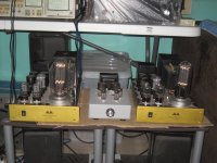
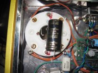
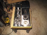
another solitary 1006 amp for repair....the elna cerafine filter cap failed as a short circuit, one rare occasion that i saw...the 6.3 v dc filament failed, even the -140 volt bias supply failed...luckily the OPT seems intact....about 450 ohms dc resistance, i have seen this go as low as 250 ohms in bad opt's...
Attachments
- Status
- This old topic is closed. If you want to reopen this topic, contact a moderator using the "Report Post" button.
- Home
- Amplifiers
- Tubes / Valves
- yet another Antique Sounds 1006 845 SET