Thanks again for your patience and time...let me be a bit more detailed about the setup I have in mind as I have the impression you think I wanted to use the 801A as power output tubes driving a speaker (your 8 Ohm example), which is not my intention.
Here is what I want to do:
Inspired by VinylSavor: The Ultimate Line Preamplifier and DAC BIG 7 and having read Allen Wright's articles and books about differential preamps, I always wanted to build a differential preamp at some point of time.
As I have build the Buffalo III in Dual-Mono, I need rather an Outputstage than a true preamp to drive my power amps. Currently I use Broskie's Unbalancer with a 6sn7 as input tube and 6n6p as cathode follower, which sums up the balanced signals to unbalanced...and the power amp ( http://www.triodedick.com/monobill/monobill schema versterker.GIF ) splits them again back to balanced...which make no sense for me.
So, the Ess9018-Dac-Chip gibes me 32mA current output, which is quiet beefy I believe. It works currently into a 20ohm resistor for a passive i/v-conversion to 640mVpk - per phase. This goes directly onto the grid of the 6sn7. The tubes bias themself correctly as the current sink in the LTP forces them to do so.
My plan: Get rid of the cathode follower and have a LTP with an line-stage-OPT, maybe even with step-down...staying differential through the whole chain.
Next stage will be the input stage of the power amp which has an input impedance of 100K. Cable between the line-stage opt and the power-amp input can be made as short as possible like 50cm/20".
I want to test different tubes in this kind of setup: 801a, 6sn7, 6n6p, 4p1l etc. Coleman regs and Kevin Carter's Current sink are already in place. Universal PSU which can deliver any HV I want as well.
So, I guess now you have an indepth overview...so, we talk aboit the line-stage-OPT of the DAC.
I understand that all the impedance and inductance principles apply here in the same way. But may I ask you to double check my assumptions:
- The Ess9018 in Dual mono with its 32mA output current should be able to drive directly the grids of the 801A as the extreme case.
- the 801A operates at 300V and 30mA heavily in class A with -10V at the grid.
- With this minus Ug the DAC can never drive the 801A into a scenario where only one tube is conducting as the DAC operates in a range of 640mV Vpk.
If these assumptions are correct:
- two tubes are conducting as this is Push-Pull and we have an effective rp of 5000/2=2500.
- Each sees half of the inductance of 210H/2=105H
- Finally, as long everything stays in class A: The Differential Push-Pull-Stage has the same low-frequency response as the SE would have had (15Hz at -1db): 210H and rp of 5000ohms vs. 105H and 2500Ohm...?
Or did I understand it wrong ?
Last edited:
I do not have the time to research one finished product, its specs, and its schematic.
And then to guess exactly what you want to change it to.
Can you draw a schematic of the DAC and first stage that you are proposing?
I do not know anything about the (dual mono?) Ess9018 DAC.
I am guessing that you are driving one DAC with MSB to LSB, and the other DAC with LSB to MSB to get the 2 phases of the signal.
Using a pair of 801As, or a dual triode 6SN7 for a particular circuit will not work without individual adjustments per triode.
Just because you have a long tailed pair does not guarantee the currents will be shared equally on the 2 phases (the DC no-signal currents).
An 801A with a mu of 8, will not have the same gain as a 6SN7 with a mu of 17 to 20.
640 mV times a gain of 8; and suppose you use a step down transformer of 4:1, now you have a gain of 2X, or 1280mV, far below the 2828mV peak output of most CD players.
But I guess that is OK, because differentially you have 2560mV peak.
For small signal operation, you can take a 5k center tapped transformer that is driven in push pull, and re-draw it as 2 triode rp's in parallel, driving a single 1250 Ohm winding.
No, the 2 tubes rp's in parallel are not driving a 2500 Ohm winding.
But if you choose to look at it that way, it is more like a single tubes rp is driving a 2500 Ohm winding.
That should give you an idea of the low frequency range, and of the load line too.
At least I believe that is the correct way to look at it.
But remember, the phases are actually opposite, and that gives the 2nd harmonic distortion cancellation that would not occur with 2 rp's in parallel driving a 1250 Ohm winding (single ended).
I hope that explains it.
Last edited:
Hi,
No, dont worry: I do not want to have you to work on my design in detail...I only want to understand this question about how does the inductance change in IT when using it in differential stage instead of SE and if my assunptions are right that diff. pair in class A will have the same bass response as SE at a given transformer with CT on the primary.
The Ess9018 works today already into a diff. pair (6sn7). Clearly the 6sn7 has more gain than the 801a, but that is not so important, I will re-gain what is missing in the first stage elsewhere (currently the summing up the signal in the cathode follower is destroying half of the gain...plus I can raise the I/V-resistor and get a much higher signal from the DAC). The circuit will look pretty simple a bit like this, but without the first transformer http://kandkaudio.com/images/Input Stage for 2 Stage PP Amp.pdf
The tubes are matched in all specs very well with utracer...so imbalance should as well be small.
It is just tohe question about the function of the IT and if I get it right:
- SE (one 801a driving the whole primary two sections connected): 210H/5000ohm/15Hz (as measured already be me)...
- will become in pushpull 105H/2500Hz/15Hz for the reasons discussed above ?
I am just not sure if I double-count the effect of two tubes always on with 105H and 2500ohm ? I have not yet build the whole thing, otherwise I would simply measure it instead of discussing the theory of it...
thx for your support ! (sorry, I was typing this in parallel to your last comment)
---------------
Ok with the explanation of your second post: It is most likely that I loose half of the inductance in pish-pull-class a, so bass response would be 30Hz -1db instead of 15Hz...I can live with this...60Hz would have been not so good...but I will measure it once it is build....
Last edited:
I will try to make it clear:
A transformer 8 Ohm secondary is loaded with 8 Ohms. You measure the complete primary impedance at mid frequencies.
Then You take the load off, and measure the complete primary inductance.
If the complete primary winding measures 5k Ohms, and the inductance measures 400 Henrys, and it does have a center tap, the following is true:
Either 1/2 winding (outside to the center tap) is 1.25k Ohms and 100 Henrys.
Now, consider a single tube with an rp of 625 Ohms that drives just 1/2 of the primary.
(for the sake of the argument, but not true in a practical way, we will ignore that the DC will saturate the core).
The load to the single tube is 1250 Ohms in parallel with 100 Henrys.
Now, consider a push pull arrangement, where one tube drives 1/2 primary, and the other tube drives the other 1/2 primary. The primary halves are in opposite phase, and so are the 2 tubes (by push pull definitions). If the 2 tubes cathodes are connected together, and are connected to a current source, and if the 2 grids are driven with a differential signal (opposite phases), then each tube Aids the other tube (if we are very well within the class A limits).
Now as to what each tube sees because of the Aiding effect, each tube sees a 2500 load, in parallel with 200 Henrys.
That is not the same as a single tube rp driving a 5k Ohm single ended transformer that has 400 Henrys (but few if any single ended transformers have 400 Henrys).
Keep in mind that if the 2 tubes are barely conducting, the tubes that has rp = 625 Ohms at moderate currents, may have an operating rp = 1250 Ohms, 2k Ohms, etc.
I have seen some data that says 801As may have rp = about 3k Ohms.
That will determine its low frequency performance if it is driving an effective inductance of 200 Henrys, when operating in a push pull or differential circuit.
I hope that all I have said is correct, and is enough for you to determine if your parts and circuit selection will accomplish what you want to do.
One thing to consider when using interstage transformers is how close to AC and Audio magnetic fields will they be, how sensitive are they to pick up those fields, versus how low a level is the desired signal at the interstage transformer.
I am not a fan of hum, nor of Audio magnetic signal feedback (positive or negative).
I believe that you are doing this with an interstage, not an output transformer. You do not have an 8 Ohm load on the secondary, but you do have what ever load on the secondary that the next stage presents (might be 100k grid resistor to ground or bias, 60pf of miller capacitance grid to plate, 3 foot coax cable, or whatever you have connected to the secondary. All of these will reflect from the secondary Back to the primary windings.
Last edited:
When thinking about your explanation, I got the impression that each time when an interstage transformer is fed by a differential signal, it sums it up on the primary and feeds an SE to the secondary which might be split by the CT-setup.
So when you drive a Karna wit its three IT with an IT of a preamp, we sum up four times and split four times ?
Well...soefar I thought it is more passing on the diff. signal 1:1 through all stages and have it summed up in the opt...
So when you drive a Karna wit its three IT with an IT of a preamp, we sum up four times and split four times ?
Well...soefar I thought it is more passing on the diff. signal 1:1 through all stages and have it summed up in the opt...
Each winding couples to the core. Each winding couples to each other if they are layered over each other, or are close side by side. The core is required for low and mid frequencies. For extremely high frequencies the windings must couple.
One point of using differential or push pull is to reduce second harmonic distortion.
It requires tubes curves to be used in opposite directions (out of phase). As one tube is on the less effective set of its curves, the other tube is in the more effective set of its curves.
The combination tends to make the sum of the effectiveness constant (linear).
The transformer has windings that are out of phase when the winding ends are referred to the center tap.
This is true for the primary, and true for the secondary.
Changing current in the primary winding(s) is what creates the changing magnetic field. The changing magnetic field is coupled to the core, and is coupled to all the other windings.
Changing magnetic fields are what creates voltage in the secondary windings.
A winding that is connected one way creates one phase of voltage. If you reverse the connections to that same winding, it creates the opposite phase of voltage. Reversing the direction of the winding changes the phase.
One method to have 2 phases is to have 2 windings. They can be, but do not have to be connected together (a center tap). That just depends on the circuit needs.
(example, 2 unconnected secondaries allows you to apply individual grid bias voltage).
As long as the core is working, and as long as the windings are coupled, then yes, you can consider that the drivers outputs are summed in the transformer.
The changing magnetic field drives each winding of the secondary. Would you call that a split, or just a change of phase?
Perhaps you are concerned, because there are so many comments about how "single ended is so much better than push pull, because it does not have to split the signal, but push pull does".
I regularly listen to my single ended amplifiers; and I regularly listen to my push pull amplifiers.
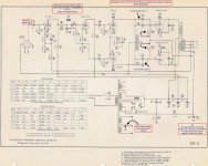
Wondering if someone can help understand the centre tapped choke used in the Brook12A design.
What happens if the centre-tapped (1800-0-1800) is replaced with two separate chokes, each 0-1800. Does it still work the same ?
A friend just built me a pair of monoblocks and I wanted to understand what happens. We just went ahead and put two single chokes in it.
It sounds brilliant, no complaints whatsoever. The 700R used for the negative bias is a source of heat and needs to be managed.
Here's a pic of the build.
Brook 12A Mono blocks
Here's the schematic.
Attachments
Last edited:
Yes, it'll just be more expensive.What happens if the centre-tapped (1800-0-1800) is replaced with two separate chokes, each 0-1800. Does it still work the same ?
CT chokes, just like PP OPTs, don't need core gap (currents in the two halves compensate each other) and thus can have more inductance per iron size.
But separate chokes benefit from the inductance being less dependent on the signal level.
Last edited:
Well, not exactly.
Actually, separate chokes do Not get the same results, versus the results with the center tapped choke.
Two separate chokes are not on the same single lamination.
That means that any 2nd harmonic distortion of one 6J5 will not be canceled by the other 6J5.
And, the driving impedance change versus signal level seen by the tapped choke is almost constant.
But separate chokes each will see a very large driving impedance change versus signal level.
And, the second harmonic distortion will not be cancelled until After it comes out of the push pull output transformer.
And when there are two or more music notes at the same time, the 2nd harmonic distortion creates Intermodulation Distortion (more tones, more distortion).
Cancel the 2nd harmonic in the driver stage. That way, the output stage does not have to deal with it.
Hmmm, it seems that those designers at Brooks may have actually known what they were doing, way back then.
Last edited:
Thanks for explaining that, most of it went over my head except the higher impedance bit.
Will this affect music in anyvway ? It's hooked up with my Altec 3way, where I've switched off the 515 bass. It sounds great, the sound is nothing like I've experienced before on these Altecs. Wholesome.
Will this affect music in anyvway ? It's hooked up with my Altec 3way, where I've switched off the 515 bass. It sounds great, the sound is nothing like I've experienced before on these Altecs. Wholesome.
Last edited:
sunil,
Lets look at the 6J5 drivers and 2A3 outputs a little differently:
Look at the top driver, and the top 2A3 (the one that it drives).
The driver has some 2nd harmonic distortion.
The 2A3 has some 2nd harmonic distortion.
The input to output phase of a triode is out-of-phase.
But we have the serial effect of two triodes, so the 2nd harmonic distortion of the driver
is partially canceled by the 2nd harmonic distortion of the 2A3.
The same effect is true for the bottom driver, and the bottom 2A3:
Partial cancellation of the 2nd harmonic distortion (again, this is a “serial” cancellation).
But we know that there is more 2nd harmonic distortion of each of the two drivers if we use 2 chokes, versus if we use the center tapped combined choke.
What that means is that the partial 2nd harmonic cancelation of a driver and its respective 2A3, will have different amounts of 2nd harmonic cancellation, depending on whether we use 2 separate chokes, or instead use the single center tapped choke.
Now part of how this all works out is also dependent on how well the driver tubes are matched, and also how well the 2A3 tubes are matched.
And then, there is the factor of the differences in the inductance of the separate chokes versus the single center tapped choke, the distributed capacitance of both, the possibility of saturation of both, and more.
It is nice to know all that.
But there is another factor that changes the overall result; the global negative feedback that the amplifier uses.
Negative feedback tends to lower distortion.
But that means that the distortion that is inside the global negative feedback loop is partially covered up (making it harder to hear certain changes that we make, such as 2 chokes versus one choke).
What you heard as a difference with 2 chokes, versus a single center tapped choke is dependent on all the above factors (and a few more, but that is enough of that).
Then there is the fact that you disconnected the 515 bass.
That did at least two things:
1. Reduced the amplitude of the bass fundamental notes from the speaker, versus the amplitude of the bass harmonics (yes, instruments have their own harmonics).
2. Made the load at bass frequencies easier for the amplifier to drive.
That is enough for today.
I have to check for any more threads, and then get some sleep.
- Status
- This old topic is closed. If you want to reopen this topic, contact a moderator using the "Report Post" button.
- Home
- Amplifiers
- Tubes / Valves
- Help me to understand the maths for anode choke / IT