Well, from jhstewart9's simulations-
So I'm thinking close to that would be nice. It's like running parallel outputs on a single socket at the low end, and five or so on the high end, depending on which tube is chosen")
I'm also thinking of trying at least one build with the 6AS7G (6N13S) as well, just need iron for it. I'm also planning a big boy build using 12AV5GA outputs, for 40~50 watts out, which may win out as far as the priority of the budget is concerned, and I have found a way to reconfigure the flea board into a Williamson style front end to drive them! I may post up a brainstorming thread on that one soon.
From the sims it appears we could expect 2-3 Watts using the 6BL7 in PP at 250-300V. The 6BX7 looks OK for 5-6 Watts. All might be less, depending on the efficiency of the OPT.
So I'm thinking close to that would be nice. It's like running parallel outputs on a single socket at the low end, and five or so on the high end, depending on which tube is chosen
I'm also thinking of trying at least one build with the 6AS7G (6N13S) as well, just need iron for it. I'm also planning a big boy build using 12AV5GA outputs, for 40~50 watts out, which may win out as far as the priority of the budget is concerned, and I have found a way to reconfigure the flea board into a Williamson style front end to drive them! I may post up a brainstorming thread on that one soon.
I built a PP 12AV5GA amp (Triode, 300V, 56ma) and it sounds very nice. Loaned it to a buddy who's been beating the snot out of it for me. He really likes it. Good for about 30W. FWIW the *DQ6B has the same if not bigger guts and costs less, if you can deal with the plate cap.
Last edited:
After ordering another set of three 12AV5GA (GE) for only $6USD shipped, only to simply add them to the twenty or so that I already have, I figure the time has come to actually build something with them, so that's the new pencil-and-paper project to take up my free time at work lately. Very little concrete design goals for that one, but the plan is 100VA toroids for output transformers for a ~3k or so load, push-pull pentode mode, and regulated ~150 volt or so screen supply. I have a 150VA dual primary/secondary isolation transformer that I added heater windings to, so it will likely use that transformer, which would have otherwise proven suitable for a 6AS7G build, albeit a bit large. I figure rectifying one winding to 160~ volts, and either the same for the other or voltage doubling it and stacking them will give plenty of voltage to play with. Time to look at voltage doubler schemes and see what makes the most. sense to get 150, 300, and 420~ or so out of a dual 115 volt secondary. Maybe simply rectifying both windings in series for ~320 volts, and capacitively coupling another bridge to that, and stacking it on the center tap? That should give ~480 or so before losses, which should work, I suppose.
Back to the flea amplifier front, I just realised that I have six russian surplus, 250 volt, 100nF K42Y PIO capacitors unused from another project, so they'll need to end up in a future flea build for sure. I might grab some motor-run PIO's for the PSU on that one too
Back to the flea amplifier front, I just realised that I have six russian surplus, 250 volt, 100nF K42Y PIO capacitors unused from another project, so they'll need to end up in a future flea build for sure. I might grab some motor-run PIO's for the PSU on that one too
Hi Ling and team,
I plan on building one of these flee amps primarily for 32R headphone usage as discussed in another thread and you suggested I build this. I have a couple of successful amp builds under my belt but am somewhat new to the hobby. I have a couple noob questions that I am pretty sure I know the answers to but want to be sure before I order parts.
1. I take it latest schematic on post #112 is for one channel only? That would mean I need 4 of the toroid output transformers for a stereo amp?
2. That would also mean that each tube shown in the schematic is 1/2 a tube per channel? So that’s one 6sl7 and one 6sn7 per channel? Four tubes for stereo?
3. Last question, the power supply in post #6 is still current and would only build one to power both channels?
Thanks a lot!
A complete stereo build needs two output transformer, one power transformer, two 6SN7, and two 6SL7. It also works great with 6N2P or similar instead of the 6SL7.
The power supply is different now, I built a simple ripple filter with a mosfet that works much better than the original, but a good choke would work too. Total power draw is around 40mA so power demands are low enough that a handful of simple styles will work well.
Post #38 is the current "blessed" design- https://www.diyaudio.com/forums/tubes-valves/303846-6sn7-push-pull-flea-amplifier-project-4.html#post5315117
The diode bridge is not shown, but is the same as earlier. A tube rectifier would also work fine, but would probably want a higher voltage transformer to be around the same as the solid state solution.
I'm in the car right now but can answer more if needed in a bit, and anyone else who reads along, feel free to contribute!
Last edited:
Ok I checked the OPT diagram, I didn’t realize it was dual primaries. I was confused when I read that primaries were in series, I assumed that it was two toroids per channel.
So I will build 2 of the post #112 circuits, 1 per channel? And then one power supply.
Also, I was planning on using turret boards but do you sell the PCB’s?
Thank you
So I will build 2 of the post #112 circuits, 1 per channel? And then one power supply.
Also, I was planning on using turret boards but do you sell the PCB’s?
Thank you
PCBs are soon getting sent out to a few folks for testing, until I have a few out there being tested I don't feel super comfortable selling them, although so far I can say that the octal (6SL7/6SN7) version is pretty much ready to go, but will likely get a few components moved around and some minor improvements as far as silkscreening to make things a bit more clear/obvious to builders. As it stands now they both look and seem to be perfectly functional and should build up just fine.
My plan is to finish up the noval-input (6N2P/6SN7) version and then send out one of each board type to those that will be checking them out. I still need to make up a user's guide, but was going to wait on first comments and possible changes before getting to far into that.
I have both versions of the board completely stuffed and ready to go, and just need to do some rather simple function checks and voltage measurements on the noval version before sending them out. I just need to cut the hole for the IEC jack, and then get it cased up and wired. Just need the time.
If you're interested in a pre-release)) version of either of the boards, at a very fair price, shoot me a PM. I have a couple left of each type that aren't yet spoken for. I'll work up a BOM and basic guide soon to go with the initial boards.
My plan is to finish up the noval-input (6N2P/6SN7) version and then send out one of each board type to those that will be checking them out. I still need to make up a user's guide, but was going to wait on first comments and possible changes before getting to far into that.
I have both versions of the board completely stuffed and ready to go, and just need to do some rather simple function checks and voltage measurements on the noval version before sending them out. I just need to cut the hole for the IEC jack, and then get it cased up and wired. Just need the time.
If you're interested in a pre-release
)) version of either of the boards, at a very fair price, shoot me a PM. I have a couple left of each type that aren't yet spoken for. I'll work up a BOM and basic guide soon to go with the initial boards.
Last edited:
Inductance it too low. The 125E spec is 11.84H. The Rl needs to be ~3X 2rp of the 6SN7 to avoid distortion in a common PP stage. So low freq rolloff would be on the high side.Hammond 125 series will work. 90 different ratios...
Over many years I've used 125Ds & 125Es, good for many low cost apps. But might be stretching for this one. For the curious & others the wdg resistances of the 125E are attached, all measured by the 4-terminal method, so very accurate.
Attachments
Did anyone find a suitable OPT of rather high impedance to match the high rp of the 6SN7.
Hammond 125 series will work. 90 different ratios...
Inductance it too low. The 125E spec is 11.84H. The Rl needs to be ~3X 2rp of the 6SN7 to avoid distortion in a common PP stage. So low freq rolloff would be on the high side.
where do you think the rolloff will end up? May still be a good choice in a multi-way (biamping) sort of setup if it isn't too high.
I need to buy a set of EI types to do a nice conventional iron build at some point, and have been thinking of the Hammonds or Edcors. May even do a real tube PSU with a rectifier tube and a choke
I'm also starting to think a parallel PCB may be a nice idea too, and I will be building some (more) speakers in 16R using some Faital Pro 3FE25-16 soon. 16R should give us a ~34K load, albeit with lower output using the toroids I used. This amplifier would be a perfect match for a Karlsonator or Cornu type of build in 16R for a desk or small bedroom, allowing for a very high quality system at very affordable cost, where large SPL isn't required.
Question for Ling: Have you thought about making a board without sockets but screw connections for use with chassis mount sockets instead?
I haven't. My preference is to use the usual spread-leg types that are so widely available. I think you may be the first I've known to actually use them on normal-ish tubes.
Too many projects, too little time.
I'm also falling for the idea of a 6AS7G build too, for a set of 4R woofers that will end up open baffle likely. I've got some russian green PIO K42 caps set aside for that one.
Last edited:
I'm also falling for the idea of a 6AS7G build too, for a set of 4R woofers that will end up open baffle likely. I've got some russian green PIO K42 caps set aside for that one.
I built one... 6WPC and LOTS of distortion. For about 40 bucks more you can build a 6P45S amp (not including the added cost of 250VA transformers) that is good for 80W in triode connection. Just saying
I ended up turning the 6N13S amp into a 6DQ6B triode connection... Less distortion, more power, less electrical demand.
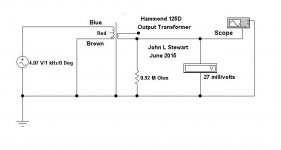
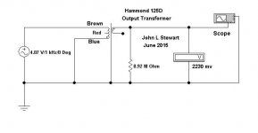
For the keeners in the audience here is more useful info related to low cost OPTs. In this case a Hammond 125D is subjected to a test to determine potential wdg capacity problems.
Low cost OPTs are wound serially, no sectioning or other fancy stuff. So the secondary ends up wound around one end of the primary. There can be as much as 150-200 pF more capacitive loading at one end of a PP cct than at the other end.
Attached is a simple way to discover which end has the most capacitive problem.
Doesn't matter much until NFB is connected. It might be one of the factors causing HF instability in the resultant cct. Worth knowing about, I've used a cap at the opposite end to equalize the load.
Attachments
I built one... 6WPC and LOTS of distortion. For about 40 bucks more you can build a 6P45S amp (not including the added cost of 250VA transformers) that is good for 80W in triode connection. Just saying
I ended up turning the 6N13S amp into a 6DQ6B triode connection... Less distortion, more power, less electrical demand.
My last real 6AS7G (6N13S) build years back was around 7-8 watts out at 1.25-1.5%, but I used the 100V/100mA/-33V g1 operating point Shoog recommended, and a bit of gNFB with the 6SL7 front end, with the red LED/47R cathode setup. I think the feedback resistor was a 820R... It worked well and increasing the supply voltage and bias yielded higher output (some 10 watts at 200 volts) but drive voltage became enormous and impractical.
That ~1.25~1.5% THD dropped to ~.3% or so under 5-6 watts and was primarily 2nd harmonic and nearly indetectable at low level, so it was still a perfectly usable amplifier. It actually had better performance in the first few watts than my EL84 (with real Mullards!) triode build using James iron and a ton of care.
I have a soft spot for the 6AS7G types for sure, and they have a certain "mojo" to them that's hard to explain. Hardly economical (not that tubes are anyway) but a worthwhile build nonetheless.
Last edited:
Very interesting. I was using 220V plate, fixed bias, 600R OPT (Yes I know that was a BAD match) and I had it biased for Class B. I also tried 100V/100ma but liked 220V/20ma better.
With the 6P45S I'm using 1k3 OPT, 300V/120ma and it makes 80W <0.3%THD and has an 8W class a limit Still the total cost difference was only about 100 CAD.
With the 6P45S I'm using 1k3 OPT, 300V/120ma and it makes 80W <0.3%THD and has an 8W class a limit
Still the total cost difference was only about 100 CAD.LF rolloff is 3db down when inductive reactance equals the source resistance.
Rl = 2*PI*f*L
So if Rl is taken as 3X the series of the 6SN7 plates, 2 X 7700rp by 3X
Plugging the numbers in we get 2(7700) * 3..........46200
Low rolloff would be ~621 Hz.
If Rl is taken as 2X rp, the LF rolloff is ~ 415 Hz.
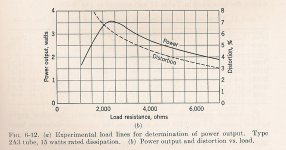
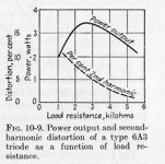
The cct needs an OPT with somewhat more primary inductance. Typical triode distortion curves lifted from EE text books.
Still worth a trial, see what happens.
Attachments
- Home
- Amplifiers
- Tubes / Valves
- 6SN7 push pull flea amplifier project