I would definitely be interested in the noval input version. This would let me use 12AT7s for the hole. From most things I have read on DIY Audio, the 'T7 has a good distortion spectrum for use in push pull circuits.
I have read this whole thread and you have been doing a great job keeping us informed of your progress. Thanks.
Ken
I have read this whole thread and you have been doing a great job keeping us informed of your progress. Thanks.
Ken
On the PCB with noval input tubes, there is enough space to put a further dual triode tube to use as extra gain stage for low output sources such as smartphones and some PC audio cards. This is the only feature I miss on current design. I also tried to add a cheap small PCB input transformer, wired as 1:4 step-up ( OEP Z218A2E , RS stock number 667-6076). It improves the outcome with the smartphone, and may be useful should a ground loop arise, but a 10x gain stage would be better.
I still use this amplifier every day and it works very well.
I still use this amplifier every day and it works very well.
I've been considering a design for a linestage that uses the edcor PCB-mount input transformers, and either a 6SN7 or even 6N16B for situations where a little bit of gain and ground isolation would be useful, but I'm not so certain including those things on this board fits the scope of the project? Personally I would like a separate PCB that could be used as a modular approach to these sorts of solutions, as it could be useful as a building block of a larger integrated design, like a full on input selector/preamp, or part of a tube active crossover or baffle step correction pre.
I'll have to draw up a few things and see what I think from there.
I'll have to draw up a few things and see what I think from there.
I think you're right. One step at a time. If this works out well, we can all talk about options like (for me) a transformer inverter stage. For that I'm going to try a point-to-point, probably with a pair of 5687s into a 1:2 step up interstage that also acts as phase inverter. But that's a separate project and mostly just an experiment for me. For now I just need to decide if I'm going octal or noval driver/inverter...
I really like the idea of a noval input stage, it's a bit more experiment friendly, since there are way more options with higher mu that work very well, and are affordable too. The 6AS7G types of build make more sense with a higher mu tube than the 6SL7, since you're not given much leftover gain for feedback if going with the 6SL7, but with a 6N2P or 12AX7 up front you'll have gain to spare for low level sources and feedback, which will be helpful.
I may order up a set of nine pin boards in the next couple days, so I can send out one of each for the test team to try. I've still not finished stuffing my first board, been too busy. I'll try and stop for cathode resistors on the way home from work so I can finish it tonight.
For anybody who cares, I'm also slowly working up a mono (two boards per amplifier) design using a nine pin front end borrowed from this amplifier, using EL84 and 6V6 types as outputs, with the option for garter bias on the output stage. It will have the option of a self biased concertina as well. Should make for a nice and easy way to build up a nice triode mode push pull amplifier, or if you're brave, garter bias works very well with pentode mode as well, from current testing") Should be able to keep each board down to 100mm square to take advantage of the very affordable 10pc/2$ deal from JLCPCB Don't let the fact that I have twenty-one NOS 6P43P-E and sixteen 6P6S (Russian 6V6GT) read anything into that at all
Should be able to keep each board down to 100mm square to take advantage of the very affordable 10pc/2$ deal from JLCPCB Don't let the fact that I have twenty-one NOS 6P43P-E and sixteen 6P6S (Russian 6V6GT) read anything into that at all
I may order up a set of nine pin boards in the next couple days, so I can send out one of each for the test team to try. I've still not finished stuffing my first board, been too busy. I'll try and stop for cathode resistors on the way home from work so I can finish it tonight.
For anybody who cares, I'm also slowly working up a mono (two boards per amplifier) design using a nine pin front end borrowed from this amplifier, using EL84 and 6V6 types as outputs, with the option for garter bias on the output stage. It will have the option of a self biased concertina as well. Should make for a nice and easy way to build up a nice triode mode push pull amplifier, or if you're brave, garter bias works very well with pentode mode as well, from current testing
Should be able to keep each board down to 100mm square to take advantage of the very affordable 10pc/2$ deal from JLCPCB Don't let the fact that I have twenty-one NOS 6P43P-E and sixteen 6P6S (Russian 6V6GT) read anything into that at all
Last edited:
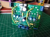
No real updates to speak of, other than I have stuffed a board without any issues whatsoever, and I have to say that they are pretty darn easy to build on. I can already see where some improvement with regards to layout and filament wiring can be made, so some of those changes have been implemented in the noval version. The input stage cathode resistors on the octal board aren't at the same area of the board, but on the noval version I was able to scoot them over for a more user friendly/symmetrical layout.
Overall I'm quite surprised at how compact these boards are! fully assembled it takes up less space than an octal Aikido preamp kit, so should make a great base for a small desktop build in one of the affordable bud industries chassis.
I just ordered a set of ten noval boards, and a set of ten mosfet PSU boards. I'll try to send out the octal boards tomorrow if possible, so anybody that was offered a sample board and hasn't yet given me their address should PM me and I'll try to send them out tomorrow afternoon.
I have a power transformer, but no suitable outputs on hand, so I'll order a set from antek today hopefully.
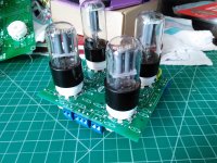
Sneak peek at the fully populated board, pretty nice! Don't mind the flux that I need to clean off, I need to grab a grubby toothbrush to scrub it off.
I ordered transformers for output, so as soon as they come in I can get this thing hooked up and going. I think I'll wait until the new PCBs come in so I can test the mosfet boards too. The 50VA 230 volt Antek power toroid I have on hand only gives 311 volts rectified, so I may do one with just a resistor divider reference, rather than zeners, otherwise I need to buy more Zeners, since all I have on hand are 51 volt 1N5262's, so I wouldn't have enough headroom to put out the voltage I want here... going forward I recommend using a 250 volt winding rather than 230, that way you have more headroom for regulation, or use with a tube rectifier and a CLC filter.
Sorry for the stream-of-consciousness style post, trying to juggle home stuff lol
Attachments
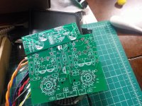
Alright, got the next set of boards in hand, I'll stuff a mosfet board and actually test the thing this weekend hopefully. The noval boards look good, other than a minor goof on my part, I've got a few holes going through my email address on the underside of the board I don't have any noval pc mount sockets on hand, so I'll have to wait to stuff one of the noval boards, but the little mosfet boards look handy already for these types of projects
I'm going to add some windings to my power supply toroid hopefully, as the 50VA anteks put out about ~311 volts rectified with the filament windings in use, and I want to try out the 300 volt build of the mosfet board, so I'm going to add some turns (maybe 75-90 or so, the 6.3 volt windings take 49 turns each) to give more headroom for regulation, as the reference string and gate threshold voltage want about 305~ volts or so, not accounting for reasonable headroom. That, or I could just build up a straight capacitance multiplier, which would work fine too for this build anyway. Either way, my son's second birthday was yesterday, and we are having his party tomorrow, so I doubt I'll be doing much hobby stuff tonight or tomorrow
I hope to send boards out soon. I still want a working tested board complete first, and then I'll send out a few.
Also, anybody have any recommendations on cheap but decent quality capacitor types for the boards? For an "official" BOM I'm thinking of doing 25-35 volt Elna for the cathodes at least, but seeing as how I'm also practically out of most of the PSU caps I usually use, I'm looking at other 350-450 volt caps in the 10uF, 22uF, and 47-100uF ranges, and want to spec something affordable that has decent lifetime and ESR ratings...
I don't have any noval pc mount sockets on hand, so I'll have to wait to stuff one of the noval boards, but the little mosfet boards look handy already for these types of projects I'm going to add some windings to my power supply toroid hopefully, as the 50VA anteks put out about ~311 volts rectified with the filament windings in use, and I want to try out the 300 volt build of the mosfet board, so I'm going to add some turns (maybe 75-90 or so, the 6.3 volt windings take 49 turns each) to give more headroom for regulation, as the reference string and gate threshold voltage want about 305~ volts or so, not accounting for reasonable headroom. That, or I could just build up a straight capacitance multiplier, which would work fine too for this build anyway. Either way, my son's second birthday was yesterday, and we are having his party tomorrow, so I doubt I'll be doing much hobby stuff tonight or tomorrow
I hope to send boards out soon. I still want a working tested board complete first, and then I'll send out a few.
Also, anybody have any recommendations on cheap but decent quality capacitor types for the boards? For an "official" BOM I'm thinking of doing 25-35 volt Elna for the cathodes at least, but seeing as how I'm also practically out of most of the PSU caps I usually use, I'm looking at other 350-450 volt caps in the 10uF, 22uF, and 47-100uF ranges, and want to spec something affordable that has decent lifetime and ESR ratings...
Attachments
Last edited:
Sheesh, you're doing all this with a 2 year old in the house? Good on ya! Mine are 13 & 15, more independent but then they have lots of activities...
I would have suggested Elna for the caps, though there are some great Panasonic low ESR caps out there. If I can dig up some specific suggestions I'll do so. Anyway, good work!
I would have suggested Elna for the caps, though there are some great Panasonic low ESR caps out there. If I can dig up some specific suggestions I'll do so. Anyway, good work!
Yep. He is way too smart for his own good. He is usually in my lap helping whenever I'm measuring resistors, mocking up parts, or doing design work on the laptop. At two years old he can already correctly use a screwdriver, put resistors into a breadboard, and loves to help out with everything he can, he is way too smart for his own good
Part of our nightly routine includes him turning off the main amplifier (while saying "night!" to it!) and then watching the tubes cool down. He's a treasure.
For capacitors, any part suggestions (preferably with links to digikey, mouser, newark, etc) would be appreciated! The film caps have a dual pattern for either 20mm axial or 15mm radial lead spacing, and the electrolytics have a 6.35mm lead spacing, with the main reservoir cap at power entry to the board having a dual pattern to also fit 7.5mm spacing... of course it's trivial to simply fit whatever you like in place by simply bending the leads a smidge. Hopefully I'll do a parts order this afternoon so I can stuff a couple mosfet and amplifier boards, as I'm planning on using one of the mosfet boards to build a big bench supply, and would prefer to grab some isolated mosfets, since I need to order PSU caps anyway. Isolated fets would mean that for most builds one could simply bolt the PSU straight to the chassis, since it's not likely to be dropping more than a watt or so in most applications.
On my build, the cathode capacitors are RS components part number 224-4404 (Rubycon YXF 10000h 105C), the 33uF filter capacitors are RS components part number 715-2325 (Nichicon CS 10000h 105c), and 10 uF filter capacitors are part number 726-0732 (Rubycon BXC 10000h 105c). My chassis is made of wood without ventilation and I selected high temperature long life parts. This was actually unnecessary because this amplifier is cold.
Good prices on those rubycon parts, and I've used them in the past so know they are good parts. I think that's a reasonable call out for the BOM for sure. 5mm lead spacing, but they will slide right into the PCB without fuss (and I'm running 5mm caps personally, I am also enlarging the through holes to accommodate multiple types, and will probably add additional holes on the next run of boards anyway)
35YXF470MEFC10X20 Rubycon | Capacitors | DigiKey
50YXF470MEFCG412.5X20 Rubycon | Capacitors | DigiKey
0.57USD each, or 4.01USD for ten is a good deal for sure too, for a 35 volt part, 0.90USD each, or ten for 6.60USD for the 50 volt version, not bad at all for a 10,000 hour part!
35YXF470MEFC10X20 Rubycon | Capacitors | DigiKey
50YXF470MEFCG412.5X20 Rubycon | Capacitors | DigiKey
0.57USD each, or 4.01USD for ten is a good deal for sure too, for a 35 volt part, 0.90USD each, or ten for 6.60USD for the 50 volt version, not bad at all for a 10,000 hour part!
For power caps, there are a bunch of good looking rubycons with a 10,000hr+ rating, but 10, 22, and 47 are the values most likely to be used here, I suspect.
https://www.digikey.com/short/j9zz5f
1.34USD each,
https://www.digikey.com/short/j9zz20
1.37USD each,
https://www.digikey.com/short/j9zznf
2.04USD each.
47uF for the main reservoir, and either 10uF or 22uF at the splitter would work well. I think for now these will be the callouts on the BOM too. If anyone has any similar parts to suggest let me know.
They have a very good price/performance ratio. I used 50V parts because they have slightly lower ESR (and to avoid stocking both 35V and 50V parts for my projects). According to Rubycon current literature, the recommended general purpose long life and low impedance series for new designs is YXJ, it has same or better specification than YXF but is smaller. The YXF parts will probably be phased out in the future, but today they are a little bit cheaper and easier to source.
I really like the rubycon caps, and they are definitely a good value and great performance.
For the coupling caps, I like axial lead poly types, but since I'm running out of my favorites (Siemens 250 volt 100nF polyester film, the yellow dudes) I've selected these 400 volt guys from Vishay-
BFC237351104 Vishay BC Components | Capacitors | DigiKey
If anybody can recommend something similar, I'm all ears, but these are very nice quality, and 0.92USD each, or ten for 7.02USD. Any 15mm box type cap will likely fit well. Alternatively, if you want what I like to use, these are my usual coupling cap for ~300 volt supply applications, and only 40¢ each-
West Florida Components - 0.1uF .1 uF 250V Axial Polyester Film Capacitor Vintage Siemens
West Florida components has some cool stuff, btw. Nice place to grab axial type caps, and a handful of other neat and useful older parts.
I've had a design drawn up for a while that is parallel outputs (4x per channel) that is fixed bias, with direct coupled ZVN0545 source followers to drive the grids. The secondaries of the output transformer are connected in series, with the center tap grounded, and either end is stacked under the cathode of each side for differential local feedback in the output stage. I figure it should be good for 7-8W or so without abusing things. If anything it should be more efficient but at these power levels, what's a little waste among friends?
Fixed bias would be a tad simpler, but loses the whole "it just automagically works" thing it's got going on. Still, it's worth a build, in my opinion. Could be a neat variant. If going fixed bias, source followers seem to be a given, too easy not too, then we can have some real fun
Fixed bias would be a tad simpler, but loses the whole "it just automagically works" thing it's got going on. Still, it's worth a build, in my opinion. Could be a neat variant. If going fixed bias, source followers seem to be a given, too easy not too, then we can have some real fun
Last edited:
What do you think of using fixed bias on this design instead? I've used it on higher power amps with toroidal PT OPTs with good success, but the power is so low I'm thinking you could just use 9V batteries for grid bias. I'm gonna kang one together and see how it is.
If you're talking about fixed bias on the output tubes, then it becomes a very different animal. It may be a terrific animal, but very different. The garter arrangement provides a measure of balance using a feedback mechanism that is worlds apart from fixed bias. Since balance in the output PP architecture is vital to the sound of a PP amp, some mechanism to accomplish that is pretty important. Particularly in my case where I want to work with 6AS7 tubes, whose dual triodes are notoriously imbalanced within any one tube (and where we're talking about a pretty big negative supply for fixed bias, not a 9v). Note though that the feedback of the garter arrangement seems, in my mind, to push the cathode bias of the output to act somewhat like a fixed bias arrangement, so I've wondered if garter bias would adopt a sound somewhere between fixed and cathode bias.
I also plan to try the 6SN7 version, though, so I'm interested in your test, particularly if you can compare it to to the garter bias of this design.
- Home
- Amplifiers
- Tubes / Valves
- 6SN7 push pull flea amplifier project