(This is exactly the sort of discussion I was hoping for! Thanks!)…
Back to the Zener idea however, would it make a big difference in ripple using a stack of Zeners close to 285290 volts instead of the 470k? This should give a more solid reference and be a bit more immune to ripple, and won't take up all that much room anyway. I know higher voltage Zeners can be noisy, but how many Zeners should I be looking at using here? 45? 10? I don't have any on hand so I would need to order some anyway.
Would we even need the CRC after the output of the "regulator" anyway? I'm thinking a small (5–6u) film cap should be plenty there. I have a bunch of 4, 5, and 6u film caps I could throw there.
To your questions: ZENER does not improve ripple. Transistor gain (or MOSFET gm) does. You use Zeners as clamps, to keep the volt-divider at some voltage that you expect every time you run the amp.
DO NOT FORGET you paper-drawing leveling capacitor. Its important.
You do not need CRC after the regulator. Just "C".
You're welcome.
GoatGuy
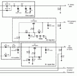
VERY nice. Tho' I was advocating Darlington NPN, MOSFET clearly works too. Good schematic. "Tuneable".
GoatGuy
Not feeling fanatical, just have limited time to work on things. I suppose a CRCRC with two 100R would work a bit better, but it's easy to add another couple parts later if needed.
Going on everything discussed, I think this is what I'll try tonight if I have the time. I could probably go smaller on the last post-fet cap (maybe 22u?) And probably could go smaller on the second CRC cap (33u?) since I'm only drawing 50mA or so, but I've got all the parts on hand, so I'll see how this does. Since I don't require "absolute" regulation, and simply need it quiet, I think the Zener version isn't required.

I have a habit of getting caught up in "analysis paralysis" and grossly overthinking things, so if this looks reasonable its what I'll try first.
Going on everything discussed, I think this is what I'll try tonight if I have the time. I could probably go smaller on the last post-fet cap (maybe 22u?) And probably could go smaller on the second CRC cap (33u?) since I'm only drawing 50mA or so, but I've got all the parts on hand, so I'll see how this does. Since I don't require "absolute" regulation, and simply need it quiet, I think the Zener version isn't required.

I have a habit of getting caught up in "analysis paralysis" and grossly overthinking things, so if this looks reasonable its what I'll try first.
Last edited:
Not feeling fanatical, just have limited time to work on things. I suppose a CRCRC with two ¹⁰⁰R would work a bit better, but it's easy to add another couple parts later if needed.
Actually the choice of 'R' does deserve some analytic choosing (over guessing). It all comes down to finding the current-draw you're expecting to deliver nominally. Let's say "100 ma" (you can scale it once we go thru this).
There are design programs of course, but I like math. You have a FWB (full wave bridge) rectifier; your line frequency is 60 Hz. Therefore there are 120 pulses of rectified AC per second. 8.33 ms between peaks.
Your first cap is 47 μF. At 100 ma, its drain rate (dV/dt) is:
dv = ∫i(t)/C dt.
Which is to say, whatever the current flow i(t) = 100 ma, divided by capacitance, over time. Let's try peak-to-peak (worst case), 8.33 ms.
ΔV = 0.1 A ÷ 47×10⁻⁶ F × 8.33×10⁻³ s
ΔV = 17.7 V
The harder analysis is what happens thru R1 and C2, to the 100 ma. In any case, a drop of 10 V is averaged by C2. The RC constant (complicated) is about 6.5 ms. You might want it higher: a multiple of 4 or so times pulse-rate. That just means changing C2 to 150 μF. Leave R1 alone.
The rest looks OK.
Only for "how it looks", I would have swapped the 470 kΩ and 10 μF holding cap left-and-right. But… that's just to “make obvious” the voltage divider.
Give a whirl!
GoatGuy
Dug through my parts, and apparently I'm stocked on 47u, but nothing smaller in high enough voltage ratings at all. The kids have drawn me away from the soldering iron for the night, so no building unfortunately, so maybe I'll go grab a few 10u caps tomorrow after work. Not enough time in the day!
Managed to at least find everything else, now to decide wether I should build the regulator on tagstrip or PCB. I'm leaning towards tagstrip, but I don't want it too sloppy with the rectifier diodes hanging about in space. I'll play with some strips and see how I can do it up nicely.
Managed to at least find everything else, now to decide wether I should build the regulator on tagstrip or PCB. I'm leaning towards tagstrip, but I don't want it too sloppy with the rectifier diodes hanging about in space. I'll play with some strips and see how I can do it up nicely.
Interestingly, I can't find much reference to garter bias, other than mentions that he wasn't the first to do it, I have a similar patent printed out somewhere but forget the number and author. The patented version has additional components however, so is not exactly similar.
I think you will like this: http://www.diyaudio.com/forums/tube...r-actually-davis-garter.html?highlight=garter
Somehow I missed that thread, but it does appear that blumlein simplified the circuit cited by Somerset. I've had a copy of the Somerset patent printed out in my datasheet/reference folder for the last few years. Is there a way to actually view the patent and related circuits from Martens? I can't see anything other than cited numbers and similar info, other than that single pic of the circuits, unless that's all there is...
I try to play it safe and simply call it garter bias, with no name attached, due to the fuzzy nature of its origins...
I try to play it safe and simply call it garter bias, with no name attached, due to the fuzzy nature of its origins...
Click on the Original Document link on the left and you can dowload the patent.
https://worldwide.espacenet.com/pub...n_EP&FT=D&date=19551109&CC=FR&NR=64203E&KC=E#
https://worldwide.espacenet.com/pub...n_EP&FT=D&date=19551109&CC=FR&NR=64203E&KC=E#
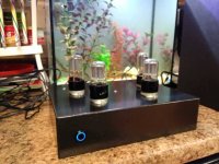
Finally 98% done-


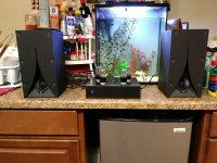
Just need to lash up the chassis ground/safety earth connections, and then bend up a little bracket to keep the power supply board still. This thing is dead silent without signal! Very clean and crisp details in the sound, even better than the prototype as far as overall quality, but the foamcore karlsonator speakers really shine and show the amplifier for how good it is.
I ended up going for a CRC preceding the mosfet with 47u/150R/47u, and the divider feeding the mosfet gate is a 10k/470k, with the 470k bypassed by a 10u cap, and the regulator is followed by another 47u cap. Very overbuilt but cheap and effective. Highly recommended.
Late to this thread but I'm very curious about your 6AS7 garter work. Did you post any threads on that here or elsewhere? Last time I looked I didn't see anything about garters and 6AS7s. Just checked and the same result. Thx.I've played with garter bias back when I was in love with the 6AS7G (which I still am) and it seemed like a natural way to go on a low power design. <snip>
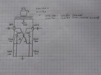
Drew up the schematic of the 6AS7 output stage, all just for you 
Ignore the notes on the 1306:4 ohm toroidal, should read 1306:8 also

Same front end that I used on this amplifier, just with a red LED instead of a cathode resistor for the input tube, and open loop (no feedback). Were I to do it again today I would also load the input tube with a CCS for more output swing. The important thing to keep in mind here, is that the input tube and phase inverter need around 300 volts to give acceptable performance, so what I did was rectify both secondaries of a dual primary/dual secondary toroidal isolation transformer, and stack them on top of eachother, giving both 160 and 320 volt supply rails. Worked great, cheap, simple. I liked it so much I built up a five channel version years ago, and might build another with toroids this year.

Ignore the notes on the 1306:4 ohm toroidal, should read 1306:8 also

Same front end that I used on this amplifier, just with a red LED instead of a cathode resistor for the input tube, and open loop (no feedback). Were I to do it again today I would also load the input tube with a CCS for more output swing. The important thing to keep in mind here, is that the input tube and phase inverter need around 300 volts to give acceptable performance, so what I did was rectify both secondaries of a dual primary/dual secondary toroidal isolation transformer, and stack them on top of eachother, giving both 160 and 320 volt supply rails. Worked great, cheap, simple. I liked it so much I built up a five channel version years ago, and might build another with toroids this year.
Last edited:
Thank you Lingwendil! Since the garter holds the grid at whatever the drop across the upper 330R is below the cathode, and given your B+, it looks like you aren't trying to swing 100v at the grid with this design. I don't want to hijack this thread, but any chance you'd be willing to answer a question or two via PM? I may start a thread of my own once I really get going on my project.
Sure, wouldn't mind at all, but some quick facts for my experiences and application (posted here so others can benefit)
6AS7 at this operation only drops 100 volts, and idles around 100mA. This only requires around a 30~32 bias voltage, which given a 300~330R cathode resistor, sets us right where we need to be with two of them stacked on top of eachother. With a 1200:8 output transformer, we can get a very nice 7-8 watts out of them. I like this operating point because it allows the use of common supply voltage, easy to source values of cathode resistors, and runs the triodes at a nice operating point. remember, these were meant for higher current at lower than typical tube voltage as regulator pass devices, so they actually work better at lower voltages, and tend to be easier to drive at such voltages.
With this set of conditions, we only need about 60~65 volts peak-to-peak drive voltage (30 per grid) which makes them much easier to drive than the high voltage applications, that can easily take 100 volts or more per grid (200+ volts peak-to-peak!) for full output, and become much more wasteful of supply voltage just to have room for the cathode biasing resistors. Fixed bias on these is a fool's errand without some sort of current mirror or bias servo to keep them in line, but garter bias works extremely well, as long as the extra dissipation doesn't bother you. I don't mind the extra heat, personally, this isn't the most efficient hobby anyways...
A 1300~ ohm output transformer can be had with a 50VA 2x115:18 toroid from Antek or similar, and will work well for these. My first builds used 8000:8 70v line transformers with a 4 ohm load on the 16 ohm tap, and worked well, but they get a bit more power out of a 1200~1500R load.
I've run them up to a 50mA/200V operating point, and it took around 75 volts of bias to do so, and they didn't measure as well at all, so I stuck with low volt operation and have been very happy with it.
Now you're making me want to build something like this. B+ from a 120V transformer, SMPS for heaters but both sections in parallel (2 6N13S per channel) Then I'm thinking an Raa of about 600R, no? And perhaps instead of garter bias I'll just use TL783s and bypass caps? OPTs could be VPT24 series 2x115:2x12... What do you think, Lingwendil?
- Home
- Amplifiers
- Tubes / Valves
- 6SN7 push pull flea amplifier project
