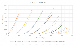
Are these by measuring 2 tubes ( strange tubes ") Or is it a scanning of the two datasheets ? They look strange anyway, not like real tubes. ib0 and ib15 has strange double kinks that i have not seen on real tubes. A uTracer and a couple of tubes could easily create real curves of real tubes.
Or is it a scanning of the two datasheets ? They look strange anyway, not like real tubes. ib0 and ib15 has strange double kinks that i have not seen on real tubes. A uTracer and a couple of tubes could easily create real curves of real tubes.
Or is it a scanning of the two datasheets ? They look strange anyway, not like real tubes. ib0 and ib15 has strange double kinks that i have not seen on real tubes. A uTracer and a couple of tubes could easily create real curves of real tubes.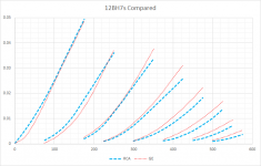
Yes, looks much more realistic. Here the trend is more visible. In a few days i will make a trace of a JJ 12BH7 and publish for comparation. ( i have grandchildren occupying my study thus it has to wait a few days)
In the meantime, here is JJ official graph, it seems most GE but not at all points.
JJ Electronic - 12BH7-A
In the meantime, here is JJ official graph, it seems most GE but not at all points.
JJ Electronic - 12BH7-A
Last edited:
That cct will need a separate heater supply for the 6FQ7.
The front end is very old topology from the time of the so-called 'Golden Throat'. Better results now from those two stages hooked up as a diff amps. Tails to -150V max. save the H-K insulation. Or FET tails.
My opinion from experimental results.
The front end is very old topology from the time of the so-called 'Golden Throat'. Better results now from those two stages hooked up as a diff amps. Tails to -150V max. save the H-K insulation. Or FET tails.
My opinion from experimental results.
Makes a better driver to drive the following stage in an RC coupled amp. The AC vs the DC loadline is an important consideration, the drive stage should have an impedance as small a fraction as possible when compared to the following stage. The 12BH7 is lower rp, should result in lower distortion.
How they compare to the ear depends on many influences external to the 12BH7. Speakers, baffle, room, mood & on & on.
Some folks like a bit of distortion. For there own reasons.
Preferences are a very complicated subject.
How they compare to the ear depends on many influences external to the 12BH7. Speakers, baffle, room, mood & on & on.
Some folks like a bit of distortion. For there own reasons.
Preferences are a very complicated subject.
If the RC cct is driving a cathode bias stage the following grid can be safely up to 500K. For that a driver of plate load 100K would be OK.
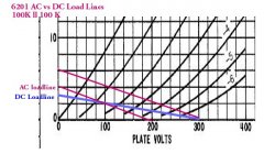
If the RC coupled cct is driving a fixed bias stage with 100K grid resister then a 100K driver would result in quite a bit of even order distortion (2nd, 4th, 6th,....). We can see the bunching up of the plate curves on the RHS of the resultant loadline. So in that case something like 27K would be a better choice.
As the following grid resistor is reduced the AC loadline rotates in a +ve direction. The example is for a different tube but applies to any RC coupled triode. And pentode.
Another point overlooked or completely missed by many is the zero order term of the power series that results. That is what moves the operating point. The effect used to be referred to as rectification. Figure that one out!!
Attachments
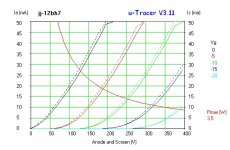
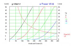
Here is curve trace of 2 JJ 12BH7
As uTracer only goes 2 400V the curves are cut there. Solid lines is triode 1,
dotted lines = triode 2
Also "summary reports" at typical conditions.
As uTracer only goes 2 400V the curves are cut there. Solid lines is triode 1,
dotted lines = triode 2
Also "summary reports" at typical conditions.
Attachments
I have yet to upgrade my u-tracer to the 400V version. all the stuff is there, but other projects have intervened.
in any event, i posed the question as I acquired a pair of the Heath WA-P2 preamplifiers which use the 12AU7 and had seen in another audio group a recommendation of the 12BH7. These quite ancient Heath preamplifiers have darned good THD characteristics. They plug into the Heath Williamson, but I have circumvented that route to use an HV regulator based upon the LT3080 and an SMPS filament source.
For the record, I am more ancient than the aforementioned preamps. They will allow me to listen to the collection of 78's I inherited.
I have yet to upgrade my u-tracer to the 400V version. all the stuff is there, but other projects have intervened.
in any event, i posed the question as I acquired a pair of the Heath WA-P2 preamplifiers which use the 12AU7 and had seen in another audio group a recommendation of the 12BH7. These quite ancient Heath preamplifiers have darned good THD characteristics. They plug into the Heath Williamson, but I have circumvented that route to use an HV regulator based upon the LT3080 and an SMPS filament source.
For the record, I am more ancient than the aforementioned preamps. They will allow me to listen to the collection of 78's I inherited.
What is your verdict about the 3 groups of 12bh7 anode curves ?
I am currently designing a power amp with MOSFET output.
- The input is the 12BH7 tube, which also provide all the voltage amplification. - The transistors in the output end just acts like an inverting buffer. As the tube inverts the outcome is in phase with the input....
Hi ! sorry to jump in but searching again for info on my beloved 12bh7 tube i find your very interesting post. Are you planning to start a specific thread for you project ?
I am going hybrid lately
Just to elaborate a little i am even loving what a humble chinese tube buffer placed between my cd and the integrated is doing to the sound. I love your concept a lot when a single very good tube takes care of all the voltage gain (10-15 times would be more than enough for me as i am using quite efficient speakers).
Tubes add a sense of space that solid state cannot provide. Moreover they seem to have a kind of magic touch with digital sources. And i can see many tube dacs around.
Any info and status on your very interesting project would be welcome and appreciated, maybe in a specific thread.
Thanks a lot indeed.
Kind regards, gino
P.S. i have some direct experience with the 12bh7 ... even placed in an old Croft Micro in place of a ecc82 provided an excellent sound. The Micro is nothing more than a pot followed by a cathode follower ... but i do not have the specific schematic. The construction is point to point and it is difficult for me to draw the schematic. The sound is so much more robust in the bass that seems unbelievable. I understand that the 12bh7 can be found in some very good sounding commercial tube power amps used as a a driver for the output stage.
Last edited:
- Status
- This old topic is closed. If you want to reopen this topic, contact a moderator using the "Report Post" button.
- Home
- Amplifiers
- Tubes / Valves
- Let's talk 12BH7