Audio source is 5v max and I believe the output impedance is 10k. I will have to verify. Amplifier is used in a mobile/portable/outdoor environment. I would like to avoid use of an opamp or BJT differential buffer stage.
The amplifier is push-pull with each output (6550) having it's own driver. This may make it easier to incorporate a transformer.
The amplifier is push-pull with each output (6550) having it's own driver. This may make it easier to incorporate a transformer.
Audio source is 5v max and I believe the output impedance is 10k. I will have to verify. Amplifier is used in a mobile/portable/outdoor environment. I would like to avoid use of an opamp or BJT differential buffer stage.
The amplifier is push-pull with each output (6550) having it's own driver. This may make it easier to incorporate a transformer.
Post up a schematic if you have one. It could be easy, or could be ~not so easy, depending on how the circuit is already set up...
Audio source is 5v max and I believe the output impedance is 10k.
5 V. is quite a bit. A "standard" CDP is 2 V.
10 Kohms is (IMO) way too "tall" for directly driving a transformer. Buffer the 10 Kohms with either a FET source follower or high gm triode cathode follower.
If the signal source is DC offset free, no cap. will be needed at the buffer's I/P. A bipolar PSU is needed.
I not modifying an existing product or have a complete schematic. I'm building a PP amp with 6550 outputs using what is essentially a Williamson amplifier. It has a gain stage DC coupled to a SLPI in one 12AU7 and another 12AU7 as the drivers to the 6550s.
What do you mean by tall? Too high of an output impedance from the source? Edcor has a CT/CT matching transformer available in a 10k:10k ratio. The impedance of the first stage is the grid of a 12AU7 with a 470k grid leak resistor. I would think the reflected impedance on the input stage primary would then be much higher then 10k.
What do you mean by tall? Too high of an output impedance from the source? Edcor has a CT/CT matching transformer available in a 10k:10k ratio. The impedance of the first stage is the grid of a 12AU7 with a 470k grid leak resistor. I would think the reflected impedance on the input stage primary would then be much higher then 10k.
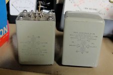
Transformer easiest -- Jensen LT-11P-1 are about $70 each. Or you can go fishing on EBay -- I picked up these Freed "trasnsitor output transformers, 600:600 for less than $20 and they are flat from about 25Hz to 100kHz with a source impedance of 20R and secondary load of 100k.
With a transformer you'll have to match the output impedance with an RC network across the secondary --
With a transformer you'll have to match the output impedance with an RC network across the secondary --
Attachments
Lose the 12AU7's. go with the far more linear 6SN7, or the 9-pin exact equivalent 6CG7. I would be inclined to use Mosfet followers to drive the outputs personally.
Here's a good read, there's a circuit posted from Miles on the last page that shows a quick scematic-
http://www.diyaudio.com/forums/tubes-valves/133034-6l6gc-ab2-amp-68.html
SLPI?
Is the gain stage a grounded cathode? If so, just simply make it into a differential, and use a good CCS for the tail. That will let you feed a balanced signal into both input tube grids.
Cascade a LTP into a LTP, with direct coupling for the first two stages. Easy peasy. Throw a 1:1+1 transformer on the input and you can drive it with most any balanced or unbalanced source with clever input jack arrangements.
Are you certain the output impedance of the source is actually 10k, or is it just rated to feed 10k? 10k is huge output impadance for most any modern source.
")
Lose the 12AU7's. go with the far more linear 6SN7, or the 9-pin exact equivalent 6CG7. I would be inclined to use Mosfet followers to drive the outputs personally.
Here's a good read, there's a circuit posted from Miles on the last page that shows a quick scematic-
http://www.diyaudio.com/forums/tubes-valves/133034-6l6gc-ab2-amp-68.html
SLPI?
Is the gain stage a grounded cathode? If so, just simply make it into a differential, and use a good CCS for the tail. That will let you feed a balanced signal into both input tube grids.
Cascade a LTP into a LTP, with direct coupling for the first two stages. Easy peasy. Throw a 1:1+1 transformer on the input and you can drive it with most any balanced or unbalanced source with clever input jack arrangements.
Are you certain the output impedance of the source is actually 10k, or is it just rated to feed 10k? 10k is huge output impadance for most any modern source.
SLPI Split Load Phase Inverter
Is a 6CG7 even in production? How about a ECC99 or 12BH7? I don't think linearity is as important as people make it out to be. Some unbalance is acceptable if not excessive. If I was doing a single-ended output with no NFB, I may agree. I'm also limited on available heater current. 12AU7 is half the heater current of the 6SN7.
Output impedance could very well be lower then 10k, and likely is, but it is 5v. That I know. The typical input impedance of line equipment is ~10k so I assumed the output impedance is equal to or lower then that. Could even be as low as 100 ohms or even 50 ohms. I know this value will play a huge roll in it's ability to drive a matching transformer. I will try and find out exactly what it is. Maybe a 600:10k transformer would be better suited.
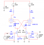
Speaking of 6SN7 -- SY's "Equal Opportunity" input stage --
That's an interesting circuit. Good balancing I assume?
SLPI Split Load Phase Inverter
Is a 6CG7 even in production? How about a ECC99 or 12BH7? I don't think linearity is as important as people make it out to be. Some unbalance is acceptable if not excessive. If I was doing a single-ended output with no NFB, I may agree. I'm also limited on available heater current. 12AU7 is half the heater current of the 6SN7.
You want to keep lower heater current, and new production availability for tubes, that's doable. JJ makes great small signal tubes.
Ah, so you're using the split-load phase inverter (cathodyne, concertina, etc) which just happens to be my absolute favorite phase inverter. If you change to a differential/long tailed pair you would get less gain, but would be balanced input. make up for the lost gain with something like the fantastically linear 12AT7, or even a 12AX7. this keeps the same heater draw, and pretty close to the same gain, depending on how you feed it. You could even go for a 12AX7 if you need the gain, and either way I would run a CCS for the tail, even the 12AX7 performs very well with a nice constant current. Do you have a negative bias rail for the outputs? If so a CCS will be very easy to implement with just a handful of parts, and you just terminate the tail into the negative rail.
Output impedance could very well be lower then 10k, and likely is, but it is 5v. That I know. The typical input impedance of line equipment is ~10k so I assumed the output impedance is equal to or lower then that. Could even be as low as 100 ohms or even 50 ohms. I know this value will play a huge roll in it's ability to drive a matching transformer. I will try and find out exactly what it is. Maybe a 600:10k transformer would be better suited.
What is the actual source you will be using? What output jacks does it have, XLR, TRS, RCA? Is that 5v per phase, or to ground? Peak or RMS? If it's a commercial product I'm sure we can pull up some helpful info...
That's an interesting circuit. Good balancing I assume?
Cross-coupled, CCS loaded, LED biased, that's the Cadillac of hybrid input stages. balance is perfect, performance should be excellent. I have simulated something similar from one of Sy's posts a while back and it gave insanely low THD numbers...
Last edited:
You still haven't said why you need high CMRR or what your source is, so I suspect this is a self-imagined need. Nonetheless, for the problem as you have described it I would go with either a pentode LTP driving the 6550's directly, or 2 triode LTP's in series driving the 6550's.
You still haven't said why you need high CMRR or what your source is, so I suspect this is a self-imagined need. Nonetheless, for the problem as you have described it I would go with either a pentode LTP driving the 6550's directly, or 2 triode LTP's in series driving the 6550's.
Automotive environment.
Automotive environment.
I not a car stereo guy, but I've routed some pretty long unbalanced interconnects in my cars that were always dead quiet.
- Status
- This old topic is closed. If you want to reopen this topic, contact a moderator using the "Report Post" button.
- Home
- Amplifiers
- Tubes / Valves
- How can I add a balanced input to a tube amplifier?