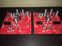
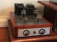
Boards are finally finished minus one back ordered capacitor. Chassis should be here next week. Its been a fun project so far. The only deviation from Pete's design is the mundorf supreme .47uf capacitors and that is only because I had 3 on the shelf. Hopefully they do the trick.
I'll be driving a pair of Klipsh Chorus speakers. I know 50 watts sounds a little light for these but honestly, the little EL84 push pull amp (my first build) drives them pretty good at moderate to loud listening levels. I am thinking this should be quite a step up as far as output is concerned.
I'll be driving a pair of Klipsh Chorus speakers. I know 50 watts sounds a little light for these but honestly, the little EL84 push pull amp (my first build) drives them pretty good at moderate to loud listening levels. I am thinking this should be quite a step up as far as output is concerned.
Attachments
The only deviation from Pete's design is the mundorf supreme .47uf capacitors and that is only because I had 3 on the shelf.
Be sure to post your impressions.
I'll be driving a pair of Klipsh Chorus speakers. I know 50 watts sounds a little light for these but honestly, the little EL84 push pull amp (my first build) drives them pretty good at moderate to loud listening levels. I am thinking this should be quite a step up as far as output is concerned.
Aren't those speakers 101dB/watt/meter SPL? With 50 watts you're firmly into rock concert territory (like The Who).
jeff
I should have posted these earlier, I finished them about a year ago, but I have been fiddling around ever since.
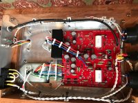
In terms of sound, they are as described in the original engineers build, and by Pete himself on his website, on the original engineers page, they are fast and clear and have plenty of power.
I am using them to drive a pair of sunflower redux, and the pre-amp is a diy SRPP+ by a great local designer.
One thing I do have to say is that as per Pete's advice you should buy a stash of the 6HJ5, I had to mess around quite a bit to get a matching pair, even with biasing. You're also may want a few extra 500ma DC rated fuses.
For me pricing and shipping weight are an issue, my currency is weak against the USD. The OTP are from Edcor, and the Power Transformers are made to Hammond spec by a local company.
The enclosure, I designed in Autodesk 360, just wanted to mention that because the deserve it for the support they give to the maker community.
Attachments
")
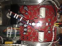
Sorry the pic of the actual enclosure was terrible.
Congrats, you did a nice job.

jeff
Hi all,
Just finished building this pair or monoblocks and powered them on for the 1st time this evening. Have an 8ohm dummy loan on the outputs and shorted the imputs. One amp is stable and ready for biasing and burn in. The dummy load on the other monoblock gets quite hot within 25 seconds of powering on and needs to be turned off. I swapped tubes between amps and same symptoms. With the tubes removed, the dummy load dosent get hot and allows me to check voltages. Voltages seem to be in the ballpark, but a bit high (tubes removed). Any advise as to how to troubleshoot this?
Just finished building this pair or monoblocks and powered them on for the 1st time this evening. Have an 8ohm dummy loan on the outputs and shorted the imputs. One amp is stable and ready for biasing and burn in. The dummy load on the other monoblock gets quite hot within 25 seconds of powering on and needs to be turned off. I swapped tubes between amps and same symptoms. With the tubes removed, the dummy load dosent get hot and allows me to check voltages. Voltages seem to be in the ballpark, but a bit high (tubes removed). Any advise as to how to troubleshoot this?
Did some more digging and double checked and all component values are correct, electrolytic caps in correct orientation, tube socket pins not shorted. With tubes removed, voltages between both amps are identical. Dummy load resistor starts smoking as soon as bias voltage starts rising.
kweaver,
I recently finished a pair and while I didn’t encounter the problems kstylianos saw, I did have a couple issues worth mentioning.
One of the two amps kept blowing a fuse. Not on first power on, but on the second. I’d turn it on and everything worked fine. But the next time I tried to turn it on, the fuse would blow. I addressed this problem by increasing the fuse value to, I think, 3.1A.
The other problem related to hum from the power transformers. This was purely mechanical hum and did not couple into the speakers. It was just the transformer vibrating on the chassis. I fixed this problem by adding some isolation washers I founds on amazon.
I’d also recommend paying close attention to the CAD drawings of the chassis. In particular notice the stand-off height between the PCB and the chassis top plate. If you use stand-offs too large, like I did, the tube sockets for the pre-tubes won’t be high enough and you won’t be able to seat the tubes in the sockets.
Now that I have things sorted, I’m quite happy with the end result - including some nice power switches with LED indicators I added to the front plate.
mike
Hi kweaver,
Terminal blocks will be fine as long as they are rated for the voltages they will see. I would normally use "barrier strips" with some fish paper (insulator) underneath so it can't arc. Thick plastic would also work. The sound will not be affected as the terminal block makes a very low resistance connection.
-Chris
Sorry I did not follow up with my inquiry. The issue was I switched the NFB leads to the board. I used similar colored zip wire for the NFB and thought I had the polarity correct. Very simple mistake that cost me hours.
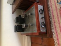
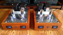
I burned them in on the bench for about 1.5 hours with 8-Ohm dummy load and inputs shorted. Continued needing to tweak bias current (55mA), but that finally settled down after 45 mins to an hour. Balance voltage pretty much stayed rock solid after 30 minutes. One of the input tubes went bad/microphonic and after replacement/rebiasing all has been well. Will continue to play them hard and check/adjust voltages as they settle in.
I'll second Mike's observations with the humming PT and making sure of correct standoff lengths. I haven't addressed the PT yet and will probably isolate from chassis as well. I cut my own out of standoffs from a spool of plastic tubing from Lowes.
An interesting phenomenon I'm noticing is that with a pair of Klipsch Heresy (8ohm) connected to either the 4 or 8-ohm tap, the bias current raises to ~70mA. This does not happen with my JMR 3ways (4ohm) or with the dummy load. Still need to figure this out.
Here's a pic with LED voltmeters turned on and amps warming up. I have some higher resolution meters on order.
Attachments
- Home
- Vendor's Bazaar
- 50W monoblock "Engineers Amp"