I recently replaced a number of components including filter caps blocking caps and supply diodes and many resistor that had gone high. I used the same values for all parts including electrolytic caps. I see that B+ for plates is 500 V where Sams's notes 470 (maybe this is VTVM vs modern meter?)?
My issue is: in Setting bias Sams calls for 34 mA and the max I can obtain with the pot is 25 or so. Tried swapping my 7355 tubes for 7591xyz and get similar results. Is the lower bias caused by the higher plate voltage?
Is the lower bias value a problem? If so, should I install a resistor to knock down the max voltage? I assume the more efficient diodes and caps caused the increase. The amp is designed for 117 Volt input.
thanks
Attachments
Last edited:
Is the bias voltage to high (to negative) ? There is a -60 and -45 as indicated values. What are those actually reading.
You could perhaps try slightly reducing R91 to say 1meg to bring it all a little more positive. It sounds like you are only a fraction off where it all needs to be.
Those more in tune with valve circuitry might have some better ideas")
You could perhaps try slightly reducing R91 to say 1meg to bring it all a little more positive. It sounds like you are only a fraction off where it all needs to be.
Those more in tune with valve circuitry might have some better ideas
Were any of the diodes you replaced Selenium Rectifiers?
Especially the diode that is used for the negative bias supply.
That might be part of the problem, because selenium rectifier stacks had quite a bit of voltage drop (replacing with a silicon diode would give a higher bias voltage).
Then there is the 117v versus whatever power voltage you have.
A tube in pentode operating mode, like you have, will not have more plate current with more plate voltage.
But ... it will have less current if the bias voltage is higher (more negative).
The 7591 has a transconductance of about 10mA per volt bias.
Suppose you have 120V power, that is a 2.5% increase over 117V.
-45V * 1.05 = 46V, or about 10mA less current (that is about what you have).
My AC mains are about 121V. That is 3.5% higher than the 117V rating of some of my amplifiers.
It can be a problem. I thought about using a 10W power resistor in series with the primary to drop the 4V difference, i.e. 4 Ohms and 1A draw = 4V drop.
(More resistance and more watt rating for more current draw, etc.)
I will have to try that.
I should be more clear. The bias voltage looks ok, its the plate current that is low. As background, I installed a one ohm resistor in series with the plate of each tube and measure the volage across it to derive the current. So, its the current that won't reach its reccommended value when I adjus the bias pot..
Maybe selenium, the parts list says they were 1N1764.
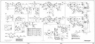
So the bias supply is outputting -45 Volts (see attached schematic, if you save it you can magnify).
So maybe this is unavoidable. I looked at the 7591 data sheet to try and understand what happens if B+ goes up, but the bias voltage, current B+ curves all look linear at the high end and stop around 450 Volts.
The bias voltage determines the anode (plate) current. If the voltage is to far negative then the valve approaches cut off and the anode current falls. It sounds like the negative voltage derived from rectifier M14 is just a wee bit to high (in the negative direction).
There are a few easy ways to bring it down a small percentage.
There are a few easy ways to bring it down a small percentage.
Sorry, I rechecked the bias voltage and the wiper of the pot reads -46.3 Volts. So I'm 1.3 Volts high.
Yes, we are talking just percentage points here. You could also look at increasing slightly the 10k feeding the bias pot.
Another possibility that you could try in addition to the above would be to add a small resistance in series with the rectifier.
Whatever you try, do it by degrees because if you have insufficient bias then then the valves will conduct heavily.
So, if I wanted the voltage back to spec, would an acceptable method be to add another diode in series with M14, doubling the drop?
You could certainly try that if you have a suitable diode. It might not be quite enough but you could see.
Its not the easiest thing to calculate.If the wiper of the pot is at -46.3 (turned to the end that gives the lowest i.e. most positive voltage) then you probably have around -63 volts rather than the indicated -60.
If the balance pots are midpoint then you have 25k +150k to ground, repeated four times. That gives a parallel resistance of 43.75k loading the bias control wiper.
So if you move the bias control to midpoint we end up with around -48.5 volts.
Now increase the 10k to 18k and you would get a swing on the bias wiper from around -45 to -42 volts.
That might be sufficient. However reducing the load on the -60 volt rail will cause it to increase slightly negating the effect a little.
Another trick would be to add a high value resistor from the wiper to ground. Something like 100k would pull enough to just lower the voltage a little. The downside of that approach is adding to the wiper current and marginally loading the supply more.
Make sure that you have all the preamp filaments in place, and running.
The -60V runs resistor and filaments in series.
See the schematic at the lower left corner.
Without that preamp filament load (with only the power amp tubes in place), the -60V supply will be essentially unloaded, and so the negative bias will be unusually high (larger negative).
The -60V runs resistor and filaments in series.
See the schematic at the lower left corner.
Without that preamp filament load (with only the power amp tubes in place), the -60V supply will be essentially unloaded, and so the negative bias will be unusually high (larger negative).
No, all of the tubes were in place when I made the bias measurement. So it is a Volt and a half more negative than it should be.
What I was attempting to say/ask was that if I followed Mooly's procedure to restore the bias to -45 Volts, was it ok to maintain the raised B+ as well. I said this because the -45 value is associated on the schematic with a plate voltage of 470 Not the 500 that I have now.
So, is -45 volts ok with 500 plate? And is 500 plate ok (or should it be adjusted also, performance, tube life etc..)?
thanks to everyone who has helped me with this!
The 7355 has ratings: Plate 500V, screen 400V, Plate Watts 18.
The 7591 has ratings: Plate 550V, screen 440V, Plate Watts 19.
500V * 34mA = 17W Plate.
So, you may be OK here, but may have a shorter tube life than you would if all the voltages in the amp are corrected.
The -60V supply may be high too. That will make the preamp filament voltages too high.
So, it appears that all the problems you are having with voltages may be mostly related to what you power line voltage is. You said the amplifier was made for 117VAC.
What is the voltage on your power mains?
Even if you solve all the voltages on the B+, and Bias, and filaments, you may end up with a hot power transformer if it has more volts on the primary than it was built for.
What about solving all this with a power resistor in series with the transformer primary.
You might pursue this solution. It is probably the easiest to implement.
But some people will say that now your power supplies will sag slightly on musical transients. I would not worry too much about that, as long as there is lots of filter caps with enough capacitance to take care of the short period of most musical transients (we are not talking about trying to max out a guitar amp for a Rock Party are we?).
Just get a guitar amp for that (and don't wonder why there is distortion when it is maxed out).
The only other solution is very expensive, and requires some real exact measurements, calculations, design, etc. A new power transformer ... but trying to get the primary voltage rating right is only the start. You would also need to have the same effective secondary voltages under the correct loads (the output impedance of each winding), and the same core losses.
Don't even go down this path.
If you want to do that, just design and build a new amp from the ground up.
FWIW- the "1.2meg" R91 at the bottom of the bias-adjust can not be correct. From inspection of 60V vs 45V, 10K and a 5K assumed centered, R91 is 47K. Not a meg. A 5K pot would make "no" difference (0.5%) in a circuit with a Meg in it.
This is probably a SAMS typo (they did that).
What do you really have there?
What if you tack-solder a 10X larger resistor across it? If you really have say 50K, then a 500K across it makes 45K and a few-volt change in extreme-hot G1 bias.
I would not over-fret 117V vs 125V wall voltage. Many tube amps thrive on modern walls.
As this fixed-bias amp draws variable power depending on signal, a simple resistor would drop variable voltage. A 120V:6V 2A filament transformer wired "bucking" would drop 125V to solid 119V, and put you closer to 1963.
> VTVM vs modern meter?
Same thing. First the "470V" line would tolerate huge meter loading. Second, most (not all) DMMs on DCV show 10Meg input loading, and the most common VTVMs showed 11Megs, same-as for most purpose. The old alternative was passive "VOM" meters. While 1K/V meters are still with us, most electronics techs would have a 20K/V instrument. On the "100V" range this is a 2Meg loading. On a 500V range it is 10Meg. So high-volt systems hardly care 20K/V VOM, VTVM, or DMM.
Last edited:
What about solving all this with a power resistor in series with the transformer primary.
Line voltage is 121 Volts.
So I could add a series resistor after M11.
(480-360)/6k=20 mA. Add to the 140 mA on 480 volt leg get 160 mA total, so 20 Volt drop can be made with a 125 Ohm 5 watt resistor (dissipating 3 Watts). You agree?
Last edited:
You have several alternatives as to how to get the voltages correct. There were several suggestions. Just pick one.
The circuits will probably work as is, except for the current in the output tube is low.
As long as the filament voltages, screen voltages, and plate voltages are within the rated tube limits, all that is left are 2 things:
1. You need to get the bias correct so that there is enough current on the output tubes.
starving it by about 10 mA per tube will not likely give optimal results, both measured power and distortion, and sound (listening results).
2. The Plate and Screen dissipation (The tube plate current times the plate to cathode voltage, and the tube screen current times the screen to cathode voltage. This needs to be checked after you get the proper current.
- Status
- This old topic is closed. If you want to reopen this topic, contact a moderator using the "Report Post" button.
- Home
- Amplifiers
- Tubes / Valves
- Stromberg ASR-880 Biasing