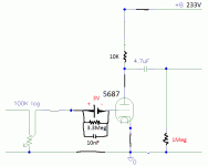
For example I want to understand the load line for 5687 tube, I have 209V as B+ and 10K as load anode resistor.
To know the plate current is to divide 209V : 10.000 ohms = 0.0209 A = 20,9mA.
Now I draw a line between these points to get the load line, If I choose the operating point at -3V as grid voltage the tube will draw 12mA, right? If I want each tube draws 10mA the grid voltage have to be -4.5V? The best OP is -7V as grid voltage?
How to know the best plate current for each tube?
Last edited:
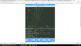
This graph give the operating point ( static point ) but you must keep in mind that when you will have some AC signal you must keep some margin on both side of the operation point ... otherwise with AC signal the tube will go to saturation ( reach maximum current ) or cutoff ( have zero current )
I am not certain I understand the question, but I can offer a little help with load lines. First you need to determine the voltage output that you expect which generally is a function of how much voltage you need to drive the next stage to saturation. Next you need to determine from the load lines the most linear region e.g., the load lines that are equally spaced. When the load lines start to bunch up is where you will get 2nd harmonic distortion.
You can see below that I have overlaid a 10k ohm load line in parallel with yours. Note the difference. You have a max output of 40V peak or 28.28 VRMS; my load line has a max output of 80V peak or 56.56 VRMS. The difference, then is that my load line can drive the next grid with twice the voltage.
You can see below that I have overlaid a 10k ohm load line in parallel with yours. Note the difference. You have a max output of 40V peak or 28.28 VRMS; my load line has a max output of 80V peak or 56.56 VRMS. The difference, then is that my load line can drive the next grid with twice the voltage.
Attachments
I am not certain I understand the question, but I can offer a little help with load lines. First you need to determine the voltage output that you expect which generally is a function of how much voltage you need to drive the next stage to saturation. Next you need to determine from the load lines the most linear region e.g., the load lines that are equally spaced. When the load lines start to bunch up is where you will get 2nd harmonic distortion.
You can see below that I have overlaid a 10k ohm load line in parallel with yours. Note the difference. You have a max output of 40V peak or 28.28 VRMS; my load line has a max output of 80V peak or 56.56 VRMS. The difference, then is that my load line can drive the next grid with twice the voltage.
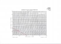
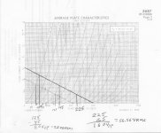
145V x 0.015A = 2.175W so is OK because the max dissipation both plates operating is 7.5W : 2 = 3.75W each triode, are ok my calculations right?
mA is only related to to make sure that I'm not violating the maximum dissipation allowed in the tube?
The question is: I'm trying to know how many mA draws each tube (to make a CCS) with B+ 233V 10K anode load resistor so max plate current 23.3mA and -3V at grid, my calculations give me 14mA, I do it right?
Attached load line pic.
Attached load line pic.
Attachments
![WP_20161218_003[1].jpg](/community/data/attachments/538/538036-df6eee0a680309a0824b4dd74b4032dd.jpg)
Last edited:
- Status
- This old topic is closed. If you want to reopen this topic, contact a moderator using the "Report Post" button.
- Home
- Amplifiers
- Tubes / Valves
- Understanding load lines