Hi,
I've just entered into the world of DIY tube amps by bringing a old Audio Innovations gen1 800 series back to life.
Only two hours ago, It played music for the first time in years!
The amp was bought second hand for the transformers and some bundled Telsa NOS tubes, still I decided to attempt repair before scraping the original PCBs.
Anyway: The amp shows clear signs of having had at least two instances of all tubes being damaged, prior to me repairing it, now for the third time.
I need advise on how to prevent this from happening again, as PCB and wiring was barley savable this time and next time the amp will definitely be history.
The damaged components indicate the failure mode is as described here: Audio Innovations
quote: "....the EL34's do their special internal short-circuit trick and destroy the cathode resistors (those who have seen their output valves glowing like fluorescent carrots before the sound expired on one or both channels ..........."
Is this an issue particular to Audio Innovations or is it general for EL34 tubes running UL Class A?
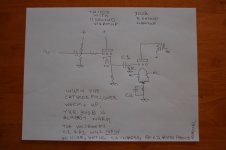
Diagram can be found here
Are there any precautions I can take to increase life expectancy of my latest pride amplifier?
Instead of EL34s I'm now using TAD 6L6 WGC-STR tubes. Matched Pairs for both left and right channels. Paraphase phase splitter is using no-name 12AU7 and input stage is Phillips Miniwatt ECC83.
There used to be a large difference (approx 10%) between Cathode resistors for "Push" and "Pull" sides. These are now within 0.5% of 395ohms.
Cathode decoupling caps had busted and are now replaced by 100V types.
Burned out grid stopper resistors on the "UL" grid has been replaced.
Unloaded B+ is 400 volts. I have not been able to measure B+ under load.
Any other measures I should take?
Thanks
Lars
I've just entered into the world of DIY tube amps by bringing a old Audio Innovations gen1 800 series back to life.
Only two hours ago, It played music for the first time in years!
The amp was bought second hand for the transformers and some bundled Telsa NOS tubes, still I decided to attempt repair before scraping the original PCBs.
Anyway: The amp shows clear signs of having had at least two instances of all tubes being damaged, prior to me repairing it, now for the third time.
I need advise on how to prevent this from happening again, as PCB and wiring was barley savable this time and next time the amp will definitely be history.
The damaged components indicate the failure mode is as described here: Audio Innovations
quote: "....the EL34's do their special internal short-circuit trick and destroy the cathode resistors (those who have seen their output valves glowing like fluorescent carrots before the sound expired on one or both channels ..........."
Is this an issue particular to Audio Innovations or is it general for EL34 tubes running UL Class A?
Diagram can be found here
Are there any precautions I can take to increase life expectancy of my latest pride amplifier?
Instead of EL34s I'm now using TAD 6L6 WGC-STR tubes. Matched Pairs for both left and right channels. Paraphase phase splitter is using no-name 12AU7 and input stage is Phillips Miniwatt ECC83.
There used to be a large difference (approx 10%) between Cathode resistors for "Push" and "Pull" sides. These are now within 0.5% of 395ohms.
Cathode decoupling caps had busted and are now replaced by 100V types.
Burned out grid stopper resistors on the "UL" grid has been replaced.
Unloaded B+ is 400 volts. I have not been able to measure B+ under load.
Any other measures I should take?
Thanks
Lars
Your transformer secondary is 310VAC? It is not clear on the schematic. 310VAC x 1.414 = 438VDC. The plates start at 438V before they are warmed up. So, All 0.47 uF capacitors should be a modern type, Not paper, and rated for 600V or 630V. I would Not use a 400V rated caps here. The B+ goes to 438V before the tubes warm up.
How many k Ohms is the ECC82 cathode resistor? It is not clear on the schematic.
Tube socket wiring is different for the 2 types of output tubes: EL34 pin 1 Suppressor EL34 pin 8 Cathode 6L6 pin1 no connect (so you can jumper to pin 8, to make it work with both EL34 And 6L6GC) 6L6 pin 8 Cathode And Suppressor
grid resistor 150k, plus 150k shared = 150k + 300k (effective/shared) = 450k Ohms. Fairly high, but probably OK for self biased tubes. I could not find a rating for EL34 grid resistor, but 6L6 specifies 500k Max for self biased tubes. the 6CA7 (EL34 “equivalent") specifies 700k Ohms.
EL34 heater is 1.5 Amps each. 6L6 heater is 0.9 Amps each. You are using 240V on a 230V transformer. The heater voltages may be high, especially for the 6L6 (less current drawn the 6.3V winding).
If the circuit is not original, or different output transformers are used, it may oscillate (negative feedback instability due to parts change).
Check the bias voltage across the 390 Ohm resistors. Bias V/390 = current. Check the Plate voltage - bias voltage, that equals Vplate to cathode. Vp-c (current) = plate + screen dissipation. Check this versus the tube ratings.
Some tubes do not work well at or near maximum voltage, current, or power dissipation. You could have “bad” tubes for this circuit.
Other than that, I do not know what can be causing a problem.
Thank you 6A3sUMMER, Your advice is appreciated.
I will make some more tests tonight and report back with measured voltages and currents.
Some initial feedback:
1 - All transformers are original, but visual inspection proves the mains transformer to be different from diagram. The one in my amp has an extra set of unused primaries. According to my repair notes the DC voltage across the PSU electrolytic caps without tubes inserted was 405 Volts. Drop to half voltage took 5 days (I have since fitted a bleeder resistor).
2 - All the 470n capacitors are "EVOX" brand MMK 400volt polyester types.
The coupling caps for the output tubes must have taken some beating in the past. Thanks for the advice - I will replace all 470nF
3 - When first powering up the amp it turned out that a hairline crack in the PCB prevented heaters on one tube from glowing. After fixing - it came up as it should and the amp is playing music: Question - Could less than one minute with B+ applied to a cold tube afflicted any damage or made changes to the tube matching?
4 - The amp is designed for EL34, The reason a I am using the 6L6WGC is simply because I got them cheap, Datasheet can be found here: TAD-6L6WGC-STR
In 3 out of the 4 EL34 tubes that came with the amp, the metalized cap had turned into white powder.
Hi there,
although the quality of current production EL34 may not be as high as in the old times, I doubt there is something like a 'special internal short trick'. It may not be the best tube, but the EL34 is heavily used in a lot of hifi and instrument amplifiers. So lots of amps would be fried regularly if that behaviour existed.
I would guess that the operating conditions in the amp in question violates one or several boundary conditions of safe EL34 operation, which provokes the described failure mode.
Regards,
Rundmaus
I second that opinion.. . .
I would guess that the operating conditions in the amp in question violates one or several boundary conditions of safe EL34 operation, which provokes the described failure mode.
I suggest to increase the screen resistors to 1, or even 2 Kohms because the main cause of power penthode failure is screen over heating, melting and falling on another electrode.
BTW, what is the voltage across each cathode resistors with no signal ?
Yves.
I second that opinion.
I suggest to increase the screen resistors to 1, or even 2 Kohms because the main cause of power penthode failure is screen over heating, melting and falling on another electrode.
Yves.
I use 1k resistors for the screens.
I have to agree with other posters, the EL34 is used a lot.
There are many very popular designs working out there with no problems.
If you abuse it then it is going to fail.
Rundmaus: That was also what I found strange, and motivated me to initiate this Thread. I also believe we have identified some issues.
I have managed to get some numbers. I'm still missing those from the Paraphase, but I do have more details from the output stage. Looking at the schematic you will se that there is a 10ohm test resistor in series with the 390ohm Cathode resistor. The 390R is decupled by 100uF.
My measured voltage across the 10 ohm resistor, actual resistor value shown (test-lead resistance compensated for) Right ch tube1 - 0.635volt/9.6 ohm = 66.1mA, value across 390R=24.4 total grid -25.0 Right ch tube2 - 0.633volt/9.7 ohm = 65.3mA, value across 390R=24.9 total grid -25.5
Left ch tube1 - 0.634volt/9.7 ohm = 65.4mA, value across 390R=25.2 total grid -25.8 Left ch tube2 - 0.640volt/9.5 ohm = 67.4mA, value across 390R=25.6 total grid -26.2
Idle PSU voltages : B+ 365v (voltage feeding PP transformer) B++ 325v (Voltage feeding ECC82 Pharaphase phase splitter) B+++241v (voltage feeding ECC83 input amplifier NOTE series resistor value not according to schematics!)
So (365-25)V*66ma Equals approximately 22W per tube.
I don't know how similar the EL34 is to my present tubes, but with my 6L6WGC being rated at 30W I guess this is safe.
I should also note that on left channel, I have added series resistance of 12 ohms to one cathode resistor and shunted the other since it was 17 ohm high. So with EL34 rated at 25W and a cathode resistor measuring 12 ohms below nominal I guess we are very close to the max limit of this tube?
Grid resistors for UL feedback grid2: Currently 100ohm, I believe an old AudioXpress article on a Marantz 8b replica also recommended increasing these. Thanks’ for the advice Yves. Unfortunately I’m not currently able to find the Marantz article. Would this change influence the global NFB/stability?
Above 6A3sUMMER recommend checking grid dissipation. How do I do this? For current I can measure the voltage across the 4K7 grid stopper, but what voltage should I use for to calculate Power?
My feeling about this amp so far is that as a minimum the Cathode resistors should be replaced/matched. If using the standard EL34 rated at 25W it would probably be advisable to increase the value to 430Ohm while at it. If staying with 390 ohms a 30W tune would be advisable. That is 6L6WGC or KT77. Furthermore, the voltage feeding the PP transformers should be checked and if more than 390volts, the 47 ohm series resistor in the PSU should b ereplaced by a 150 ohm as indicated on the scematics. This will reduce B+ voltage by approximately 26 volts. Increasing the grid stopper for UL feedback should be considered. It may be advisable to reduce the two 150K resistors between control grid and gnd, but further measurements should be done so as to determine if this would adversely affect grid dissipation. Would you agree on these conclusions?
I also suggest that the 6L6GC-STR is probably not a safe choice in this circuit either, at minimum the cathode bias resistors need to be changed for a 6L6GC. I've generally found modern 6L6s to be less rugged than EL34 regardless of the designated type.
Kevin, I didn’t see your reply until I had made my previous posting.
With my measured numbers, do you still feel I should increase the cathode resitor values? If so, to what value?
I guess I can increase the 10 ohm resistors used for measuring bias to, lets say 33 or 47 ohm, but since they are not decoupled gain will be reduced (and linearity improved?).
Will a change like this also influence output impedance?
I should ad that, once I am happy that the output tubes will last I aim to experiment with removal of NFB and re-doing the Paraphase phase splitter into a long-tailed-pair configuration.
I calculated around 25W dissipation for the 6L6 in your current circuit which ought to be just fine, comfortably under the maximum. The relatively low plate voltage helps, I'm used to much higher voltages with EL34 (up to 500V or so) and fixed bias.
The long tailed splitter would be a definite plus I think, less sure about deleting the GNFB unless you are considering running triode connection and have speakers that are suited to the higher resulting output impedance.
The long tailed splitter would be a definite plus I think, less sure about deleting the GNFB unless you are considering running triode connection and have speakers that are suited to the higher resulting output impedance.
I could not see the schematic, but take a few minutes to test the biasing circuit. Perhaps, the negative temporarily drops to a too little value( false in any solder, a bad cap, a bad diode, etc) leaving the tube with less bias than normal, and an overcurrent in it destroys them. A point to see, is if the bias is independently adjustable, to check the potentiometers/preset if it is not making poor contact between the carbon track and the movable arm.
Once I saw 3 6KD6's integrally destroyed in a hf equipment (Perhaps a Yaesu FTDX400) whose negative bias was disappeared as the electrolytic cap became shorted out.
I also suggest to make all test using an incandescent in the primary, or still better in series to the B circuit (plus or minus Ebb), then in case of temporarily overcurrent, you can anticipate it looking the bright of the lamp, also it acts as a current limit for the tubes. Us e a lamp whose power capability is about the same expected in the dut.
Good luck.
A big thanks to everybody who has responded. I have learned a lot, and keep learning!
Increasing the grid resistor for the UL grid as first recommended by Yves and Nigel above will definitely happen.
On-line investigation show the original Mullard 520 amp to use 1K as proposed above.
The Marantz 8B replica article I talked about earlier used to be available at the Piltron transformers web site. Unfortunately, with their new web site the download link no longer works.
I was able to find part a partial printout that I once made and would like to quote: "....inserted a 500 ohm resistor into the screen grid circuit of the final tube. Mr Barber, formerly of Svetlana suggested this value via email. It might be safer to protect the screen grid from the overcurrent drive of EL34 than the 100 ohm usually found. The value of 500 ohm will not degrade the sound Mr. Barber said..."
I will not pretend to understand the mechanism behind this failure mode or how the resistor increase effect UL feedback, frequency response or NFB, but will take good advise when I see it!
I can only assume the higher resistor will lower screen grid dissipation. In addition I guess the UL feedback at higher frequencies will be reduced due to grid capacitance and since my OPTs have different DC resistance between UL tap and B+ for the push and pull tubes their working conditions will now be more similar.
Furthermore: What about the lack of grid resistor on the phase splitter input. Is this good practice and can it cause issues?
On the input tube, the Cathode voltage is 1.1 volt (according to diagram). If musical peaks on the input goes higher than this, I assume the grid-cathode voltage will be positive? Might this effect stability?
I am not familiar with electrolytic capacitors failure modes, but can confirm that I had to replace cathode decoupling capacitors. Two of the cathode decoupling caps where dried out and a third had exploded. This could back up Osvaldo's theory that negative bias disappeared due to internal short in one cap. Original caps were 63 volt types, the new are rated at 100v.
Original caps were 63 volt types, the new are rated at 100v.
This isn't a good idea. When there is a big difference between the working voltage and the rated one, the capacitor doesn't finish its formation, then, lower capacitance is the result Use the nearest higher value that the expected in the circuit. For example, for a 12V supply use 16WV, not 100WV.
Bypass Capacitors:
The Ratio of 16V cap / 10V cap = 1.6
The Ratio of 1.6 times a 63V cap = 100.8V capacitor That is OK.
The Ratio of 63V cap and 25V bias is 2.52 That is OK.
Depending on how tubes and circuits warm up, the self bias voltage can be much higher at warm-up than during normal warmed-up operation.
I have used much larger ratios, for example I used a 200V cap to bypass 60V (Ratio 3.17). That is because it was the only part I had at the time. So is that OK? Yes. You need to measure the capacitance on a DMM that has a capacitance measurement. Many bypass caps are rated for -20%, +10%. A 100 uF cap that measures 80uF or 110uF is within its rating. Whatever it measures on the DMM, it will almost certainly be at least that much capacitance when it is operating in the circuit.
Some reasons that negative feedback is used are: Lower Distortion (especially of less linear stage(s), i.e. pentode and to a lesser degree ultralinear) Lower Output Impedance (Higher Damping Factor) Wider Frequency Response (make up for frequency response roll-off of the parts and circuitry)
One of the most overlooked causes of low frequency roll-off is the capacitance of the cathode bypass cap. What is overlooked is that you need to bypass Both the cathode impedance and the self bias resistor (in your case 390 Ohms) that is in parallel with it. This is especially important if no negative feedback is used, since a roll-off here is not corrected. And if negative feedback is used, it must make up for this (the less feedback has to make up for, the less the amount of negative feedback is required). The less the amount of negative feedback that is used, the less likely that instability will occur when the amplifier is working into a loudspeaker’s complex impedance. The amp has a harder time working into a loudspeaker than into a resistor load.
Suppose a coupling cap and grid resistor combination is -1 dB at 20 Hz. And suppose an output transformer is -1 dB at 20 Hz. And suppose an output tube cathode bypass cap is -1 dB at 20 Hz. If there is no negative feedback, the amplifier will be (-1) + (-1) + (-1) dB = -3 dB at 20 Hz.
EL34 From Triode to Ultralinear to Pentode mode the transconductance is about 11,500 micro mhos. That means the cathode impedance is about 87 Ohms. The parallel of 87 Ohms and 390 Ohms = 71 Ohms When the capacitive reactance is 1/10th of the parallel capacitance, the low frequency response will drop by 1 dB (-1dB). 1 / (71 Ohms x 2 x pi x 20Hz) = 1,137 uF. If you open the feedback loop, you will need to use a 1000uF part. (for -1 dB at 20 Hz)
6L6GC From Triode to Ultralinear to Pentode mode the transconductance is about 4700 micro mhos to 6000 micro mhos. That means the cathode impedance ranges from 213 Ohms to 167 Ohms. The parallel of 213 Ohms and 390 Ohms = 138 Ohms 1 / (13.8 Ohms x 2 x pi x 20Hz) = 576uF. A 500uF part will work here If you open the feedback loop, you will need to use a 500uF part. (for -1 dB at 20 Hz)
The parallel of 167 Ohms and 390 Ohms = 117 Ohms 1 / (11.7 Ohms x 2 x pi x 20Hz) = 680 uF. A 680uF part will work here If you open the feedback loop, you will need to use a 680uF part. (for -1 dB at 20 Hz)
Again all very interesting and educational
I plan now is to check grid leak currents at next opportunity. I do have a set of (un-matched) KT66 tubes and I am trying to get hold of a pair of EL34 tubes just to repeat the cathode and leakage tests.
Actually, the KT66s leave only 4-5mm (<1/4 inch) between the bottles – is this safe for a test or am I better of leaving them in the drawer?
After that I will dig out some measurement equipment try to get some reference measurements before doing starting modifications.
I will definitely have to start a separate thread when I get to that stage!
6A3sUMMER: Very enlightening on Cathode bypass capacitors. I guess these numbers are a good argument for using fixed bias with amps that does not have negative feedback - If there is no cathode resistor there is nothing to bypass!
Last edited:
Were able to access and measure 3 out of the 4 resistors located between UL tap and the screen grid. Voltages are between 250-300 mV. Measured over 100ohm resistor this equates between 2,5-3mA going into the grid. Voltage between grid and ground measured at 363 volts. Does that mean that there is approximately 1W screen dissipation?
Can this be varying with conditions? I had some "bad" measurements on one difficult to access resistor. Unless the probe was on the wrong resistor, I can swear I saw just above 2 volts on a couple of occasions!
Finally: There is approximately 5 cm (2") PCB track between tube and resistor. Is there any point to minimize this when swapping the resistors?
?
Fixed Bias versus Self Bias KT66s Spacing too close Screen Dissipation PCB traces
Adjustable Fixed Bias Advantages:
Less B+ Voltage required (no self bias Voltage drop). Can adjust for exact current (but just need to get close).
Adjustable Fixed Bias Disadvantages:
Needs a separate bias adjust for each tube, because of the following: Matched tubes may not be matched when installed in the amplifier you are using them in: different B+; plate load resistances not exactly matched; push pull transformer primary DCRs are not equal from one side to the other; tubes drift over time to be less matched.
Have to go back and forth between tube potentiometers, changing the bias on one tube can change the standing current on another tube. This is an iterative process.
One coupling cap, one grid return resistor, one potentiometer, and one current sense resistor per Each tube (4 parts per tube). must use one grid stopper resistor for Each tube, (but this is the same as for self bias).
Have to adjust each time a tube is changed. Needs to be re-adjusted over time. Hard to care for. Tube rolling is a pain.
Self Bias Advantages:
No need to adjust bias when changing tubes. Tube currents are close enough automatically.
Only one coupling cap, and only one grid return resistor for parallel tubes (or for single tubes in push pull, one coupling cap, and one grid resistor for each side: one set for push, and one set for pull). (2 parts per tube).
Tubes tend to drift together over time. No need to adjust bias when tubes age.
Easy to check each tube current, Bias voltage/resistance = current. Easy to care for. Tube rolling is easy.
Self Bias Disadvantages:
Need higher B+ Voltage to make up for self bias voltage drop.
Need a separate resistor and capacitor for each tube (2 parts per tube; 2 less per tube than for fixed bias). One grid stopper resistor for Each tube (but this is the same as for fixed bias).
The KT66 spacing of 5 mm is far to close. But if you use a fan on them during very quick biasing and testing it is OK. Have your bias set on the larger voltage setting, and then turn the bias down until you get the desired current. Then you can use them on your next amplifier design, built on a larger chassis.
For fixed bias circuits, you will need a cathode resistor to be able to measure the voltage so you can calculate the cathode current. You can use a 1 Ohm resistor, if your DMM can measure mV. 65 mV = 65 mA, etc. The amp you have makes this simple. But some people use 2 or 3 output tubes in parallel per side of push and pull. That requires a lot of potentiometers for push pull, and a lot of setting to get it right.
You can see why I like self bias. Design the plate volts, draw a load line on the tube curves, calculate the cathode self bias resistor (desired bias voltage / desired current = self bias resistor Ohms). Now when you power it up, just verify what the volts and current are. Finish measurements of power out, distortion, look for oscillations, etc. Then you are ready to listen.
You had 1 watt of screen dissipation on 3 of the tubes, that is OK. But … If you have 2 Volts across a 100 Ohm screen resistor, that is 20 mA, Whew! With 360 volts on a screen, that is 7.2 Watts! That is running pretty hard! 6L6GC screen maximum rating is 5 Watts EL34 screen maximum rating is 8 Watts, but I would not run it there. KT66 3.5 Watts design max, 4.5 Watts absolute max Better find out what is happening here.
I would not worry about 2 inches of PCB trace for a screen resistor. I would worry about a long lead from a grid stopper resistor to a control grid.
Excepting the case of DC coupled circuits between two or more stages, or a severe malfunctioning of a single stage, no one cathode will go over its normal voltage during warm up or heating. It always go from zero to the normal value.Depending on how tubes and circuits warm up, the self bias voltage can be much higher at warm-up than during normal warmed-up operation.
If you have in your stock such a big isolation capacitor, you may use it, but if you will buy a part for a specific use, it is best to use an insulation voltage closer and a bit higher to the expected normal value. Higher capacitor values has also bigger inductances, which can cause phase alterations very unpredictable, much more important when the amplifier has feedback, positive or negative. Also they are bulkier, heavier and expensive than a smaller unit.
Yes, it is true that you should not use an electrolytic cap that is rated for several times the voltage that it will see in the circuit it will be used in. I am attaching a schematic of an application where the bias voltage can rise far more than the value it stabilizes too.
Some direct heated triodes warm up to full current in about 2 to 4 seconds. Some indirectly heated triodes warm up to full current in about 11 seconds (almost no current for the first 5 to 7 seconds.
"All generalizations have exceptions"
Some direct heated triodes warm up to full current in about 2 to 4 seconds. Some indirectly heated triodes warm up to full current in about 11 seconds (almost no current for the first 5 to 7 seconds.
"All generalizations have exceptions"
Attachments
It's g2 dissipation at issue, so you need to measure current through the 100R series resistors, and voltage between cathodes and g2's, then multiply the two results to obtain power. Use volts and amps to obtain watts, of course. But will very likely be fine..........Above 6A3sUMMER recommend checking grid dissipation. How do I do this? For current I can measure the voltage across the 4K7 grid stopper, but what voltage should I use for to calculate Power?
Intermittent meltdown of power valves, generally suspect g1 coupling capacitors in cathode biased circuits like this ?
HTH !
LD
- Status
- This old topic is closed. If you want to reopen this topic, contact a moderator using the "Report Post" button.
- Home
- Amplifiers
- Tubes / Valves
- EL34 Internal shorts