It is quite interesting to read the comments and noted that with this concept, many see the chip amp as the master and the triode as the servant - where this servant adds distortion to the master chip amp. In reality, this is a valid viewpoint. And if we see it this way, then the concept is a daft one.
But this is a tube forum and I am surprised to see people do not treat the triode as the master and the chip amp as the servant. The master wants to drive the loudspeaker but do not have the muscle to do so, hence he asks the servant to do the donkey job. But in doing so, the servant must follow the master's way exactly and do not contribute to anything else other than power.
Nevertheless, this finally boils down to your own taste. After listening to this for 2 days, I believe this is a very good sounding amp. More listening to come.
the issue isn't master or slave in these two pieces.
The master should be the source.
The amplification chain should the the apocryphal "wire with gain". Thats where your amp falls down - it (perhaps intentionally) injects distortion to match an expectation of "tube-yness".
Some feedvback wrapped around the entire thing might correct that, but would likely remove all "tube-yness" in the output - except for that warm glow, no doubt located high and up front on the chassis.
No matter how you see it, the result is multiplication of complex transfer functions. Period.
The only good thing that I see, input impedance of the triode that is high and more linear, less frequency dependent than of the chip amp, so the result of it's load of the source could be beneficial.
The only good thing that I see, input impedance of the triode that is high and more linear, less frequency dependent than of the chip amp, so the result of it's load of the source could be beneficial.
Last edited:
I find it amusing that some people worry about resistor linearity (and choose particular brands) while others deliberately use a much more nonlinear element, such as a triode (as used here) or an LDR (as used in some volume controls).
More like the valid viewpoint. In this circuit the triode has a minor role as a cathode follower, and a major role as part of the feedback network. It is definitely a chip amp with added triode distortion. If you wanted to make a triode amp with added output power you would add a solid-state follower to a grounded cathode stage.FYC said:In reality, this is a valid viewpoint.
Member
Joined 2006
Nice to see a successful implementation of Tubecad's STC amp in action. ")
I am more familiar with Kamijo san's STC designs:
www2u.biglobe.ne.jp/~hu_amp/amput3e.htm
and his VFET- LM3886 amp is very intriguing and I hope to finish building it someday soon!
https://translate.googleusercontent...ep.htm&usg=ALkJrhjuCNT8_aWNoI4lkbtjSeYEADIorg
I am more familiar with Kamijo san's STC designs:
www2u.biglobe.ne.jp/~hu_amp/amput3e.htm
and his VFET- LM3886 amp is very intriguing and I hope to finish building it someday soon!
https://translate.googleusercontent...ep.htm&usg=ALkJrhjuCNT8_aWNoI4lkbtjSeYEADIorg
Funny to see that TubeCad finally embraced the STC circuit.
Back in 2003 he commented negatively (on TubeCad) on a similar variant:
http://www.diyaudio.com/forums/tubes-valves/20686-se-sound-p-p-amplifier.html
In any case, it is a good thought experiment for understanding N Fdbk. And has a functional utility for SET purposes.
Another way of looking at it: is as a V amplifier (tube) and an I amplifier (SS) in parallel, called a composite amplifier by some, where the feedback seeks to minimize the loading on the V amplifier by minimizing current variation in it (by controlling the I amplifier). Nothing wrong with such an approach.
One could get even more carried away, by using V AND I feedback to control the I amplifier. To set a specific output Z.
Or placing the I amplifier output after (at the secondary) of an OT for the V (tube) amplifier. Then the tube can do some heavy lifting as well.
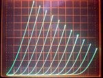
And if you use a "perfect triode" for the feedback (or V amp), no reason it has to be distorting:
and (a tube veneer amp) just puts the final finish on the sound. (requires a very low Z secondary OT if the tube amp is smaller than the SS amp; has to be able to drive the same final current level):
Back in 2003 he commented negatively (on TubeCad) on a similar variant:
http://www.diyaudio.com/forums/tubes-valves/20686-se-sound-p-p-amplifier.html
In any case, it is a good thought experiment for understanding N Fdbk. And has a functional utility for SET purposes.
Another way of looking at it: is as a V amplifier (tube) and an I amplifier (SS) in parallel, called a composite amplifier by some, where the feedback seeks to minimize the loading on the V amplifier by minimizing current variation in it (by controlling the I amplifier). Nothing wrong with such an approach.
One could get even more carried away, by using V AND I feedback to control the I amplifier. To set a specific output Z.
Or placing the I amplifier output after (at the secondary) of an OT for the V (tube) amplifier. Then the tube can do some heavy lifting as well.
And if you use a "perfect triode" for the feedback (or V amp), no reason it has to be distorting:
and (a tube veneer amp) just puts the final finish on the sound. (requires a very low Z secondary OT if the tube amp is smaller than the SS amp; has to be able to drive the same final current level):
Attachments
Last edited:
Member
Joined 2006

Huh. Kamijo san seems to have come up with the STC type ideas first for tubes, as far as I know. An independant re-invention here from thinking alike. The four basic composite amplifier approaches were published a long time ago in IEEE. Many variations around.
Last edited:
and (a tube veneer amp) just puts the final finish on the sound. (requires a very low Z secondary OT if the tube amp is smaller than the SS amp; has to be able to drive the same final current level):
Also it has to be EXTREMELY FAST since solid state distortions are of quite high order. ;-)
Back in 2003 he commented negatively (on TubeCad) on a similar variant:
http://www.diyaudio.com/forums/tubes-valves/20686-se-sound-p-p-amplifier.html
:
Thanks for the link and the info. Very interesting.
I did add a delay relay to avoid the power up issue that can damage the loudspeaker. The 6SN7 spec says warm up time ~ 10s, and I actually put in 20s delay. Speaker is connected quietly as I observed. Only when I power off, there is a very small "click" sound. Very small and should not be a big problem.
On DC offset, the TubeCAD version use 2 1M resistors to control. I measure about 30mV DC in both channels.
The only thing left now for me to consider to to add a DC speaker protection in conjunction to the time delay.
In this circuit they aren't really in parallel. Remember, the anode is the tube input here. All the gain (V and I) comes from the chip; the triode is not much more than a bad feedback resistor.smoking-amp said:Another way of looking at it: is as a V amplifier (tube) and an I amplifier (SS) in parallel, called a composite amplifier by some, where the feedback seeks to minimize the loading on the V amplifier by minimizing current variation in it (by controlling the I amplifier). Nothing wrong with such an approach.
In this circuit they aren't really in parallel. Remember, the anode is the tube input here. All the gain (V and I) comes from the chip; the triode is not much more than a bad feedback resistor.
Good cathode follower + bad feedback resistor. If to add a honest feedback resistor from cathode to input of the chip the result will be much better.
"In this circuit they aren't really in parallel. Remember, the anode is the tube input here. All the gain (V and I) comes from the chip; the triode is not much more than a bad feedback resistor."
True. But one can look at the parasitic forward path of the triode as an attempt to affect the output. The Op amp (etc), which monitors its current, prevents it from changing its current by supplying all the AC load current. An extreme case obviously. (some finite resistance below the cathode would allow the tube to start having some effect)
True. But one can look at the parasitic forward path of the triode as an attempt to affect the output. The Op amp (etc), which monitors its current, prevents it from changing its current by supplying all the AC load current. An extreme case obviously. (some finite resistance below the cathode would allow the tube to start having some effect)
Last edited:
I did build two STCs with tubes - ECL82 - and they did work OK. One was sold.
Maybe this is not a topology for purist, but for us who want to try out new stuff it's worth trying even if it is "just for fun".
Else, mixing vacuum and silicon may result in interesting stuff.
When talking OTL and tubes I have to finish my OTL SE hybrid amp with Russian 6S31B pensize tubes as drivers an FETs 2SK1058 feeding the speakers. However no Triode feedback.

Kick him back!
I have tried the transistors alone, no tubes, and they work fine and sound OK. In a way it could have been fun, but I assume that the end result don't match the extra work.
It does!
Here is what I did back in 1970'Th, a transistor output stage that sounds as clean as tube one, but sadly does not glow!
Attachments
if you have built a tube amplifier circuit using mosfets instead of triodes, you will find that it sounds much different as well as have more gain.
output mosfets will require ~8 volts on gate to achieve proper operating currents with cathode (now source) resistors unchanged.
depletion mosfets used for 12ax7 , 6922 , 6SN7 etc
output mosfets will require ~8 volts on gate to achieve proper operating currents with cathode (now source) resistors unchanged.
depletion mosfets used for 12ax7 , 6922 , 6SN7 etc
Last edited:
- Home
- Amplifiers
- Tubes / Valves
- Super Triode Connected (STC) chip amp