Any more updates here?
Stc is very interesting. I've read all of jp early work.
seems like the perfect balance of 2h/3h can be obtained.
Too looks like a more elaborate local feedback arrangement.
A good thing...
Doing a prototype now, can't wait to hear.
But now puts more pressure on my test eqpt ie oscillators and analyzers.
Wish I had noticed Stc three years ago.
-
Attachments
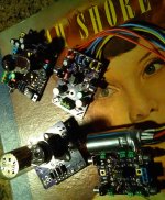
Took one of my previous boards and re-configured as a real STC, yep this is what I've been looking for. In fact can tone it down. Plenty of range to play with.
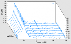
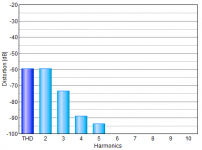
This plot is 1khz, with 2khz dominant harmonic, a 4th is there but no dirty 5ths. So STC is real. 6SN7-SA5532 used here. Mid level drive.
What is nice , you can tap the high fidelity output or STC output or pan mix both.
-
This plot is 1khz, with 2khz dominant harmonic, a 4th is there but no dirty 5ths. So STC is real. 6SN7-SA5532 used here. Mid level drive.
What is nice , you can tap the high fidelity output or STC output or pan mix both.
-
Attachments
i do not think H2 is a magic pill , just want the ability to inject (without pots) an H2 level that is a known constant percentage of the signal.
That is ability to throttle up-down .05% to 2% and bypass.
So far with the limited time on it, as of today ,selecting hi-med-lo gain tubes is only method. Of course thats fun too.
It can be done solid state but just not sounding the same to me. Not sure why.
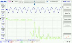
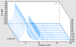
This is a JJ 12AX7 plot shown with identical signal levels, one is STC mode and other is normal mode which mirrors the generator signal. SA5532 op-amp. The vertical scale is uncalibrated. Voltage 250mv RMS. Unity gain and +-15VDC supply. No high voltage.
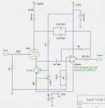
If you want to know what STC super triode mode is , look at some of the published data on it. Very simple thesis, a triode vacuum tube is placed in feedback of amplifier to flavor entire signal. Thats it.
-
That is ability to throttle up-down .05% to 2% and bypass.
So far with the limited time on it, as of today ,selecting hi-med-lo gain tubes is only method. Of course thats fun too.
It can be done solid state but just not sounding the same to me. Not sure why.
This is a JJ 12AX7 plot shown with identical signal levels, one is STC mode and other is normal mode which mirrors the generator signal. SA5532 op-amp. The vertical scale is uncalibrated. Voltage 250mv RMS. Unity gain and +-15VDC supply. No high voltage.
If you want to know what STC super triode mode is , look at some of the published data on it. Very simple thesis, a triode vacuum tube is placed in feedback of amplifier to flavor entire signal. Thats it.
-
Attachments
Member
Joined 2009
Paid Member
> H2 level that is a known constant percentage of the signal.
"Natural" H2 varies with signal level. Your ear "knows" this.
"Constant" H2 can be computed with frequency doubling. Which is typically also level dependent and not pure H2. And full of intermodulation when used with multi-tone signal (speech/music).
"Natural" H2 varies with signal level. Your ear "knows" this.
"Constant" H2 can be computed with frequency doubling. Which is typically also level dependent and not pure H2. And full of intermodulation when used with multi-tone signal (speech/music).
> H2 level that is a known constant percentage of the signal.
"Natural" H2 varies with signal level. Your ear "knows" this.
"Constant" H2 can be computed with frequency doubling. Which is typically also level dependent and not pure H2. And full of intermodulation when used with multi-tone signal (speech/music).
It may indeed do variable level 2H, I have not fully characterized. Maybe specific to some tube type don't know. Going to listen for a few weeks and see.
I'm not understanding why the 3H disappeared. It definitely was on input, and re-appears on normal output. Normal meaning the op-amp outer closed loop vs the pre-distortion output.
But on the 2H tap the 3H is gone.
Doing it all analog, the processor route has real limitations and assumes we know everything to be modeled. Plus analog way more fun.
-
Had some time to look for variable h2-h3 ratio.
This is still using a 6SN7/SA5532 . Large anodes seem to make a difference on low-voltage vs B9 style glass. Lower noise and fewer surprises.
I put a bypass across the triode so it can be varied 0-100% which equates to 0-5% THD.
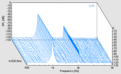
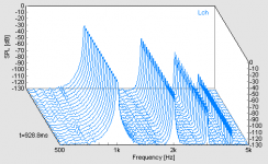
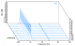
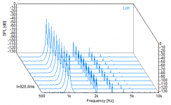
These plots show the 0.1 % THD selected, then a one percent THD selected showing a variation in the h2-h3 ratio based on amplitude. (So it does vary the ratios.)
Last is zero % THD which displays the op-amp and sound card distortion.( tube is bypassed )
No 'tits' are observed until about 5 Vrms in highest triode mode.
Now doing a stereo board / line-buffer based on this info. The switching supply mounted on pcb did not work out well. So going back to dedicated analog supply.
This is still using a 6SN7/SA5532 . Large anodes seem to make a difference on low-voltage vs B9 style glass. Lower noise and fewer surprises.
I put a bypass across the triode so it can be varied 0-100% which equates to 0-5% THD.
These plots show the 0.1 % THD selected, then a one percent THD selected showing a variation in the h2-h3 ratio based on amplitude. (So it does vary the ratios.)
Last is zero % THD which displays the op-amp and sound card distortion.( tube is bypassed )
No 'tits' are observed until about 5 Vrms in highest triode mode.
Now doing a stereo board / line-buffer based on this info. The switching supply mounted on pcb did not work out well. So going back to dedicated analog supply.
Attachments
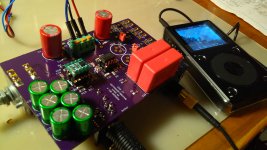
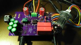
Testing a few days before installing tubes.
The red jumpers allow bypassing tube feedback for AB comparisons.
The OPA1622 does excellent job driving my Grado SR125.
Otherwise a 5532 can be used as line output buffer.
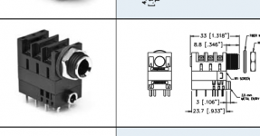
No more RCA connectors. Using the 1/8-1/4 stacked connector.
The red jumpers allow bypassing tube feedback for AB comparisons.
The OPA1622 does excellent job driving my Grado SR125.
Otherwise a 5532 can be used as line output buffer.
No more RCA connectors. Using the 1/8-1/4 stacked connector.
Attachments
Tube rolling now. 12bh7 sill best so far.
The h2 level is dynamic, very noticeable on acoustic guitar using Johnny Cash's final albums.
It's like an extra dimension.
The temporary 1k resistors seen are used to set h2 max levels.
Pots on order , till later.
The h2 level is dynamic, very noticeable on acoustic guitar using Johnny Cash's final albums.
It's like an extra dimension.
The temporary 1k resistors seen are used to set h2 max levels.
Pots on order , till later.
Attachments
I'm re-spinning a new board with tilt tone adj. So more delay before publishing schematic.
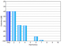
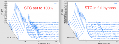
Here is the basic fft with H2 set to min and max. Notice the op-amp's chain 3rd is totally gone when set to max. Still looking at this as it may be preferable for some third.
Calibration is set using a 1khz tone and raising H2 level control until the harmonic is audible, then back off slightly. The h2 level is then present but not intrusive. It ends up around 0.25% thd.
-
Attachments
Hi,
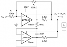
My knowledge of op amps is very basic, so I need a little bit of help in understanding how to adapt FYC’s circuit in post #1 of this thread with the OPA541 in master-slave.
John Broskie is very fond of the OPA541, especially in master-slave arrangement. He likes the doubling of current and the reduction of distortion by 20db. (Power Boosters)
Mr. Broskie mentions that he uses 1M resistors for the Super Triode OPA541 - feedback and + to ground to keep the dc offset “extra low”. I’ve never seen an op amp used in unity gain arranged in this manner.
Does anyone know a resource (webpage or section of a book) that can help me directly understand this use of an op amp to help me figure out adapting these circuits?
Is there a simple way to adapt the OPA541 in master-slave to FYC’s Super Triode circuit?
I've included images of both circuits.
Thank you very much - ziffel
Attachments
Last edited:
...Mr. Broskie mentions that he uses 1M resistors for the Super Triode OPA541 - feedback and + to ground to keep the dc offset “extra low”. I’ve never seen an op amp used in unity gain arranged in this manner. ...
I've seen it far too often. Maybe you are younger.
Opamp inputs suck current. Assume 1uA. We need 1Meg on one input so an appropriate servo cap can be film not electrolytic. 1uA in 1Meg is 1 Volt. If we only do that on one input, then there will be 1V offset.

Is 1uA reasonable? No, but '5532 can suck over 200nA, 0.2uA, 0.2V in 1Meg, so not too far off.
FET input amps, even the humble TL072, can run 1Meg with low error. (However the baked-in offset may be several mV.)
Thank you, PRR.
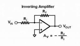
I'm used to simple inverting op amp circuits, with input and feedback resistors (see image).
With the circuit Mr. Broskie used, would I use NO resistor for unity gain? This is where I get confused.
I assume I would use a 100k input resistor with the 1M feedback resistor to obtain 10x gain. Is this correct?
Attachments
- Home
- Amplifiers
- Tubes / Valves
- Super Triode Connected (STC) chip amp