Thanks Koonw,
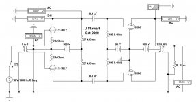
I'm using your PL519 model in the attached schematic.
This is the FFT at 100 Wrms:
This is the FFT at 90 Wrms:
This is the FFT at 80 Wrms:
This is the FFT at 60 Wrms:
I'm using your PL519 model in the attached schematic.
This is the FFT at 100 Wrms:
Code:
Harmonic	Frequency	 Fourier 	Normalized	 Phase  	Normalized
 Number 	  [Hz]   	Component	 Component	[degree]	Phase [deg]
    1   	1.000e+03	5.573e+01	1.000e+00	   -0.58°	    0.00°
    2   	2.000e+03	3.662e-02	6.570e-04	  -97.22°	  -96.64°
    3   	3.000e+03	2.414e+00	4.332e-02	   -4.25°	   -3.68°
    4   	4.000e+03	2.957e-02	5.305e-04	   83.82°	   84.40°
    5   	5.000e+03	1.250e+00	2.244e-02	  170.34°	  170.92°
    6   	6.000e+03	5.839e-03	1.048e-04	   72.12°	   72.70°
    7   	7.000e+03	1.656e-01	2.970e-03	  -51.08°	  -50.50°
    8   	8.000e+03	7.157e-03	1.284e-04	 -159.41°	 -158.83°
    9   	9.000e+03	1.805e-01	3.239e-03	    1.14°	    1.72°
Total Harmonic Distortion: 4.898948%(4.907856%)
This is the FFT at 90 Wrms:
Code:
Harmonic	Frequency	 Fourier 	Normalized	 Phase  	Normalized
 Number 	  [Hz]   	Component	 Component	[degree]	Phase [deg]
    1   	1.000e+03	5.388e+01	1.000e+00	   -0.62°	    0.00°
    2   	2.000e+03	2.331e-02	4.327e-04	 -100.87°	 -100.25°
    3   	3.000e+03	1.460e+00	2.710e-02	   -2.69°	   -2.07°
    4   	4.000e+03	2.688e-02	4.989e-04	   77.60°	   78.22°
    5   	5.000e+03	9.466e-01	1.757e-02	  173.19°	  173.80°
    6   	6.000e+03	5.865e-03	1.089e-04	  131.94°	  132.56°
    7   	7.000e+03	2.392e-01	4.439e-03	  -26.77°	  -26.15°
    8   	8.000e+03	6.782e-03	1.259e-04	  -91.46°	  -90.84°
    9   	9.000e+03	1.089e-01	2.022e-03	   28.97°	   29.58°
Total Harmonic Distortion: 3.267444%(3.278462%)
This is the FFT at 80 Wrms:
Code:
Harmonic	Frequency	 Fourier 	Normalized	 Phase  	Normalized
 Number 	  [Hz]   	Component	 Component	[degree]	Phase [deg]
    1   	1.000e+03	5.152e+01	1.000e+00	   -0.64°	    0.00°
    2   	2.000e+03	1.144e-02	2.220e-04	  -99.98°	  -99.35°
    3   	3.000e+03	6.315e-01	1.226e-02	    0.87°	    1.51°
    4   	4.000e+03	2.546e-02	4.943e-04	   82.75°	   83.38°
    5   	5.000e+03	5.915e-01	1.148e-02	  178.55°	  179.18°
    6   	6.000e+03	4.573e-03	8.875e-05	 -144.73°	 -144.09°
    7   	7.000e+03	2.523e-01	4.897e-03	   -9.08°	   -8.44°
    8   	8.000e+03	3.422e-03	6.643e-05	  -41.26°	  -40.63°
    9   	9.000e+03	7.038e-02	1.366e-03	  137.63°	  138.27°
Total Harmonic Distortion: 1.755570%(1.762551%)
This is the FFT at 60 Wrms:
Code:
Harmonic	Frequency	 Fourier 	Normalized	 Phase  	Normalized
 Number 	  [Hz]   	Component	 Component	[degree]	Phase [deg]
    1   	1.000e+03	4.400e+01	1.000e+00	   -0.62°	    0.00°
    2   	2.000e+03	1.712e-02	3.892e-04	   89.93°	   90.55°
    3   	3.000e+03	1.568e-01	3.563e-03	  177.96°	  178.58°
    4   	4.000e+03	6.780e-03	1.541e-04	   92.16°	   92.78°
    5   	5.000e+03	2.985e-02	6.785e-04	 -174.11°	 -173.49°
    6   	6.000e+03	7.501e-04	1.705e-05	   75.11°	   75.73°
    7   	7.000e+03	3.707e-03	8.425e-05	   40.64°	   41.27°
    8   	8.000e+03	5.003e-04	1.137e-05	   99.96°	  100.58°
    9   	9.000e+03	3.349e-03	7.612e-05	 -153.27°	 -152.65°
Total Harmonic Distortion: 0.365262%(0.365283%)
Attachments
6DK6 PP in Triode First Pass
Altho I have data sheets from JJ, Amperex & Svetlana none shew the value of triode mu. But from previous experience & some other clues taken from the information available it appears the mu is 2.5>3.0>3.5. I've set mu at 3 for the simulation. Other than max plate dissipation the results are much like what is possible with the 6080/6AS7G family.
For the conditions shewn about 28 Watts is available at clipping. I've used a 6BL7 instead of a 6SN7. The 6BL7 is like a 6SN7 on steroids.")
Fixed bias on low mu triodes makes me nervous, thermal runaway is always a possibility.
More later.
Altho I have data sheets from JJ, Amperex & Svetlana none shew the value of triode mu. But from previous experience & some other clues taken from the information available it appears the mu is 2.5>3.0>3.5. I've set mu at 3 for the simulation. Other than max plate dissipation the results are much like what is possible with the 6080/6AS7G family.
For the conditions shewn about 28 Watts is available at clipping. I've used a 6BL7 instead of a 6SN7. The 6BL7 is like a 6SN7 on steroids.
Fixed bias on low mu triodes makes me nervous, thermal runaway is always a possibility.
More later.
Attachments
Last edited:
A Comparison
Over time I'd seen many attempts to drive low mu triodes such as the 6AS7A/6080 series. None appeared adequate in one way or another. Some were simply brute force. The most difficult part to design in these amplifiers was the driver. There had to be a better way.
McIntosh, Electrovoice & the Circlotron all used boot strapping for the driver stage, why had no one tried that on the 6080 series. So I wired a rough version using the UL taps on the OPT to provide the boot strapping. On the bench, the results were very good.
For the final version the OPT is a Hammond special H300429 set for a plate to plate impedance of 2150 Ohms. The UL taps are at 40 %.
The resulting amplifier has a Damping Factor of 3 with no NFB. With 13 db the DF is 15. This amplifier was published in Glass Audio Magazine, May 1999. Depending on the power supply, 25-30 watts is available at clipping.
The Final Amplifier claims a DF of 40. I think that to be very unlikely. UL usually gets a DF of approximately one for internal impedance of 8 Ohms on the 8 Ohm tap. NFB of 10 db would reduce the internal resistance by a factor of 3.16, so the internal resistance would be 2.53 Ohms. That would be a DF of 3.16. Perhaps the original measurement yielded a DF of 4 for the Final Amplifier.
My thoughts, anyway.
Attachments
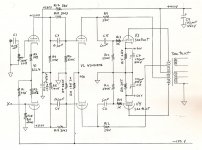
To drive 6С19П tubes in my Constellation-T amp I used higher anode voltage for the driver. In the driver I used ГУ-17 twin tetrode as LTP.
Constellation-T2
Constellation-T2
Thanks Koonw,
I'm using your PL519 model in the attached schematic.
This is the FFT at 100 Wrms:
Zintolo,
Thanks for sharing your simulation results. Is this what you expected? And thanks for your simulation input file. The latter I would find it very useful once I become Spice-capable.
Meanwhile, where do you think most higher power distortion originates, is it the UL EL509 power, phase splitter/inverter or 12AT7 voltage amp sections? What did you use in your simulation for the inverter tube?
......
The resulting amplifier has a Damping Factor of 3 with no NFB. With 13 db the DF is 15. This amplifier was published in Glass Audio Magazine, May 1999. Depending on the power supply, 25-30 watts is available at clipping.
The Final Amplifier claims a DF of 40. I think that to be very unlikely. <snip> Perhaps the original measurement yielded a DF of 4 for the Final Amplifier.
Thanks for reminding me of your published design of this bootstrapped 6AS7 amplifier in Glass Audio. I remember seeing it back when. I will have to dig my old copies out. What distortion did you measure just before clipping at 25-30 watts? I assume this was achieved with the two triode sections of each 6AS7 tube in parallel.
Do you think bootstrapping would be a good approach to improve the performance of the “Final Amp” EL509 amp? I guess the Final Amp design is not so final yet
It would be nice if Mr. Kjeld Pedersen would join the discussion. Perhaps he could clarify the DF also.Thank you Mr Stewart, may I ask you why?The Final Amplifier claims a DF of 40. I think that to be very unlikely.
Thank you very much Francois, I will work again on the schematic and repost the correct one, with all right parameters.The latter I would find it very useful once I become Spice-capable.
I still need to check it, I just made the system simulates converging with reasonable times to the results. I then simulates a CCS on the driver, but seems not to improve too much the situation.Meanwhile, where do you think most higher power distortion originates?
I used an ECC81 for the PI.What did you use in your simulation for the inverter tube?
Please read #64 carefully. If you differ tell us why & give a technical account of your thoughts.Thank you Mr Stewart, may I ask you why?
The products listed on that web site are very impressive. Throw enough money at a project & anything is possible. For the amps shewn the 6336 family is a very good starting point. Six of those in PP I think 100 Watts is not a problem at all.
The DF of 70 would be difficult even with triodes. But no circuit information is given. I'll have a look at that with some simulations sometime in the next few days. Winter is coming here, there are other things to do.
I've never used the 6336, they were available during my time in the research lab. But we never had a need for anything like that so I've never had a chance to design into anything. The 6336 was meant for regulated power supplies, for that I've used 6080, 6AS7G, 6L6, 6W6, 807, KT88 & 6550 & 304TH.
Thanks Koonw,
I'm using your PL519 model in the attached schematic.
This is the FFT at 80 Wrms:
Code:Harmonic Frequency Fourier Normalized Phase Normalized Number [Hz] Component Component [degree] Phase [deg] 1 1.000e+03 5.152e+01 1.000e+00 -0.64° 0.00° 2 2.000e+03 1.144e-02 2.220e-04 -99.98° -99.35° 3 3.000e+03 6.315e-01 1.226e-02 0.87° 1.51° 4 4.000e+03 2.546e-02 4.943e-04 82.75° 83.38° 5 5.000e+03 5.915e-01 1.148e-02 178.55° 179.18° 6 6.000e+03 4.573e-03 8.875e-05 -144.73° -144.09° 7 7.000e+03 2.523e-01 4.897e-03 -9.08° -8.44° 8 8.000e+03 3.422e-03 6.643e-05 -41.26° -40.63° 9 9.000e+03 7.038e-02 1.366e-03 137.63° 138.27° Total Harmonic Distortion: 1.755570%(1.762551%)
Roberto,
Still pondering your simulation work and how to interpret the results. What does the widely varying phase degree (last column) mean?
I noticed that the original poster Tube Mania (in post #1) measured .5% distortion at actual 26Vrms output (~85 watts into 8 ohm I assume). Your simulation shows 2.5 time that distortion at 80 watts. Any thoughts on the cause of the difference?
If I understand it correctly, your simulated schematic shows Vbias as -90V and ~65 ma bias current, while Tube Mania has -75V bias on the output tubes, with 80 ma current. Could this be it? I’m not sure how the UL output is simulated though.
Kind regards,
Francois
Last edited:
I saw it in many simulations. Pass talks about the importance of the phase of the second harmonic (most people prefer it negative in blind tests), but not so much about others.What does the widely varying phase degree (last column) mean?
LTSpice models, working points, approximations (it could have been optimized in real life to cancel harmonics)Your simulation shows 2.5 time that distortion at 80 watts. Any thoughts on the cause of the difference?
at -75V the bias was too hot in the simulation, that's why I lowered its value. I will do some more tests for sure!If I understand it correctly, your simulated schematic shows Vbias as -90V and ~65 ma bias current, while Tube Mania has -75V bias on the output tubes, with 80 ma current. Could this be it? I’m not sure how the UL output is simulated though.
- Status
- This old topic is closed. If you want to reopen this topic, contact a moderator using the "Report Post" button.
- Home
- Amplifiers
- Tubes / Valves
- Special offer for skilled tube fanatics