Hello. My first post here so I hope I've got the right bit.
I've been collecting old gear to make myself a valve amp and found this old hand made amp in a junk shop. I bought it and some other bits and pieces for £3, which seemed like a bit of a bargain. I don't think its going to be much use for parts in my intended new build so I thought if I could find out a little more about it I might just rebuild it in a less lethal and more attractive form. It would at least provide me with some experience before starting to build from scratch.
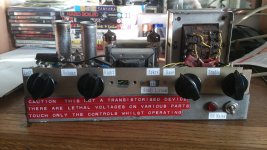
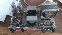
The valves are EZ81 rectifier, ECC83 and 2x ECF80s on the left and 2x EL84s in the middle next to the output transformers. The power transformer is a 350v ct type. Theres not much in the way of makers names that I can find on any of the main components.
If anyone knows anything about it or if there's a schematic available it would be appreciated.
I've been collecting old gear to make myself a valve amp and found this old hand made amp in a junk shop. I bought it and some other bits and pieces for £3, which seemed like a bit of a bargain. I don't think its going to be much use for parts in my intended new build so I thought if I could find out a little more about it I might just rebuild it in a less lethal and more attractive form. It would at least provide me with some experience before starting to build from scratch.
The valves are EZ81 rectifier, ECC83 and 2x ECF80s on the left and 2x EL84s in the middle next to the output transformers. The power transformer is a 350v ct type. Theres not much in the way of makers names that I can find on any of the main components.
If anyone knows anything about it or if there's a schematic available it would be appreciated.
Attachments
It reminds me a bit of some of the kit stuff I used to see advertised in issues of Practical Wireless about 45 years ago.
The power transformer does not look like the one originally intended for this device. As implemented this thing is extremely dangerous due to all of the exposed terminals on the power transformer. I'd cover the terminals with tape temporarily and get a cover made if you are going to restore this thing.
It seems to be a bit of a hodge podge of parts and technology decades apart, either that or as it appears its been bodged to the hilt.. lol
The two electrolytics at the rear of the chassis should probably be replaced, as should the output tube (EL84) coupling capacitors. Other parts may need to go too.
It looks like a basic EL84 SE stereo amp with a passive tone control stage and one stage of make up gain.

Bassy,
I agree about it being 100% "home brewed".
I count 5 tubes, not 6. Are you sure about the complement?
The "iron" could be transferred to a new chassis. However, unless the new chassis is deep enough to permit "burying" that apparently salvaged power trafo, a safety cage/cover has to be fabricated for said item.
A straight forward "5" WPC stereoblock could be implemented with a 12AX7/ECC83 and 2X EL84/6BQ5s.
I agree about it being 100% "home brewed".
I count 5 tubes, not 6.
Are you sure about the complement?The "iron" could be transferred to a new chassis. However, unless the new chassis is deep enough to permit "burying" that apparently salvaged power trafo, a safety cage/cover has to be fabricated for said item.
A straight forward "5" WPC stereoblock could be implemented with a 12AX7/ECC83 and 2X EL84/6BQ5s.
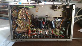
I can only guess that maybe it was a console type amp that has been retooled? The curious bit is the old style waxed circuit board. That indicates a commercially made amp. I suppose it may have been a kit like Kevin mentioned. The bottom picture shows that someone has added new caps to the mix so it has been worked on some. cheers
Bassy,
I agree about it being 100% "home brewed".
I count 5 tubes, not 6.
The "iron" could be transferred to a new chassis. However, unless the new chassis is deep enough to permit "burying" that apparently salvaged power trafo, a safety cage/cover has to be fabricated for said item.
A straight forward "5" WPC stereoblock could be implemented with a 12AX7/ECC83 and 2X EL84/6BQ5s.
Thanks for all the replies. The sixth (EZ81) valve is hidden behind the power transformer in the photos, tucked away at the back. I agree it appears to be cobbled together and messy in its present state. I'm not going to try and restore it, its just too dangerous. When I got it home I plugged it in, stood well back and flipped the switch with a bit of wood. The valves did at least light up so something's working but I don't think its worth a lot of work.
Would anyone be able to suggest a schematic I could work from to recycle some of this gear? I'm working to a tight budget and seeing as this is my first attempt at a build it would be good to use stuff I already have.
Would anyone be able to suggest a schematic I could work from to recycle some of this gear?
Send member Tom Bavis a PM. He has an extensive collection of schematics. One of the old, SE, console amps should be a good place to begin.
BTW, what kind of signal source do you plan on using? If a "standard" CDP, with a 2 VRMS O/P, is the signal source, you really don't need a preamp. 10 Kohm log. taper controls cap. coupled to the 'X7 sections' grid to ground resistors (use 100 Kohms there) is all you need. FWIW, I'd use 0.56 μF. between the controls and the grid circuitry. That will protect those small O/P trafos from a deep bass error correction signal, which they can't handle. You should be able to play a "standard" double bass, which reaches down to 41 Hz. Don't even think about 32 foot organ stops.
Do you own an oscilloscope? An o'scope is needed for fine tuning GNFB phase compensation. However, a brute force method is available, should you lack the instrument.
Would anyone be able to suggest a schematic I could work from to recycle some of this gear? I'm working to a tight budget and seeing as this is my first attempt at a build it would be good to use stuff I already have.
I would recommend removing the valves and transformers and throwing the rest away . The 47uF capacitors may be worth saving . The mains transformer looks like it may be past it's prime . I don't think the output transformers will perform miracles but if the valves are good , you have the parts to at least get a project up and working with the addition of a handful of inexpensive parts
316a
316a - That's what I was thinking, keep the transformers and valves and scrap the rest. I had a go at the power transformer with a multimeter and it seems to be putting out the voltages it says it should be, so hopefully that's reusable if I can find some kind of cover to make it safe. Failing that I could bury it inside a chassis where its out of harms way.
Send member Tom Bavis a PM. He has an extensive collection of schematics. One of the old, SE, console amps should be a good place to begin.
BTW, what kind of signal source do you plan on using? If a "standard" CDP, with a 2 VRMS O/P, is the signal source, you really don't need a preamp. 10 Kohm log. taper controls cap. coupled to the 'X7 sections' grid to ground resistors (use 100 Kohms there) is all you need. FWIW, I'd use 0.56 μF. between the controls and the grid circuitry. That will protect those small O/P trafos from a deep bass error correction signal, which they can't handle. You should be able to play a "standard" double bass, which reaches down to 41 Hz. Don't even think about 32 foot organ stops.
Do you own an oscilloscope? An o'scope is needed for fine tuning GNFB phase compensation. However, a brute force method is available, should you lack the instrument.
Eli - I'll message Tom Bavis and see what he suggests. I did have a look at the Mullard book and there's a schematic in there for a stereo amplifier of 7 watts which uses similar stuff to this one. It doesn't seem too complicated to build. Nevertheless I get the feeling I'm at the start of a steep learning curve.
I'll mostly be using the amplifier with CDs and MP3s but may get a turntable in the future. I'd rather not complicate things too much at this stage so something that plays CD audio is fine for now.
I don't own an oscilloscope and to be honest I'm not sure what GNFB phase compensation is. I'll spend a bit of time Goodling this stuff when I get a quiet afternoon.
Sure looks like a Dynaco Mark II or III chassis so don't toss it as it could be used or sold down the road.
Maybe make a cover for the PS transformer for sure or even the whole amp. Open transformers are common from some makers and yours is probably good.
I would see how it sounds (it might surprise you with new caps) remembering that tube amps always need a load
(speakers or big resistors of about 25W) or you risk the Output Transformers.
Normally you could use a dim bulb tester in series with a variac to slowly reform the caps to try it. In the end it's best to replace the coupling caps, PS & bias caps or you also risk the transformers. Better sonically and more reliable also.
Then just replace one cap at a time so things don't get mixed up. Check resistors to see if they still come close with the tubes out also. Tubes used there are in production and are likely good.
Follow Kevin's advice on the caps for sure!
It may be designed off of a really good circuit so give it a chance!
Another option if it works is to build a nice radio cabinet in nice wood for safety/looks as some production gear from back in the day looked much the same also behind their wood shells/cabinets.
Last edited:
Hi,
For £3 you can't go wrong. Salvage what you can and start again.
Assuming they are SE output transformers take a look at :
Easy-to-build SE amplifier ⋆ Lundahl Transformers
Obviously details and power will be different, but
I like the very novel output stage arrangement.
rgds, sreten.
For £3 you can't go wrong. Salvage what you can and start again.
Assuming they are SE output transformers take a look at :
Easy-to-build SE amplifier ⋆ Lundahl Transformers
Obviously details and power will be different, but
I like the very novel output stage arrangement.
rgds, sreten.
316a - That's what I was thinking, keep the transformers and valves and scrap the rest. I had a go at the power transformer with a multimeter and it seems to be putting out the voltages it says it should be, so hopefully that's reusable if I can find some kind of cover to make it safe. Failing that I could bury it inside a chassis where its out of harms way.
My concerns about the mains transformer is the physical state of it . Iron of this age can sometimes be problematic and can throb at power on or mechanically buzz in use . Try leaving it powered on with the secondaries unconnected and see if it gets warm after a few hours . I would suggest gutting the amp and building a prototype on a piece of wood . Once you have a working setup , build a suitable chassis , allowing plenty of space around the parts
316a
GNFB = global negative feedback. No o'scope means brute force methods, which is not the end of the world.
Please upload or link that Mullard schematic.
This is the book I found the schematic in, its the 10 watt stereo amp, not 7 as I said in the previous post. Is a 1950s design likely tolerate a CD input?
Hi,
For £3 you can't go wrong. Salvage what you can and start again.
Assuming they are SE output transformers take a look at :
Easy-to-build SE amplifier ⋆ Lundahl Transformers
Obviously details and power will be different, but
I like the very novel output stage arrangement.
rgds, sreten.
That does look reassuringly easy to construct. I would have to buy some new valves and a choke and figure out how to get the right voltages. I'll give this one some thought.
That does look reassuringly easy to construct. I would have to buy some
new valves and a choke and figure out how to get the right voltages.
I'll give this one some thought.
Hi,
I meant a lower power version using the EL84's and your trannies.
Just apply the principles outlined, and ask for help if stuck.
Nearly all voltages and values will be different.
Try the free TinaTi circuit emulator.
rgds, sreten.
- Status
- This old topic is closed. If you want to reopen this topic, contact a moderator using the "Report Post" button.
- Home
- Amplifiers
- Tubes / Valves
- Help Identifying A Valve Amplifier