I know the benefits of using a CCS for the plate load of a gain stage, but is there any particular benefit of using a CCS in place of a resistor in the cathode of a cathode follower (either for a preamp or for headphone amplifier purposes)?
I ask because I just built a headphone amp with a simple LM317 biased at 50mA current draw in the cathode and 210V at the anode of the EL84 (configured as a triode), but find it clips very quickly into my Beyer T1 (a 600R load).
I can't get it to good listening volumes before clipping, and was wondering if I should just switch to a resistor.
Any help is appreciated!
EDIT: the title should read: "Does it make sense to use a CCS instead of a resistor in the cathode of a cathode follower?"
Last edited:
What's your headphone impedance? A CCS is very convenient to use in CFs, but remember that your loadline will be dominated by the headphones- if they're 30 ohms (say), that will be a tough load and you'd expect premature clipping.
They are 600 ohm impedance.
a quick picture (schematic) or the circuit would help. Is the CCS AC bypassed at all?
I drew up a quick schematic of the output stage that I need help with.

What DC is the grid referenced to?
The plate of the gain stage going into the grid of the output stage is at about 170 VDC
So effectively, you have 30V on the EL84 plate. There's your problem.
If I used a capacitor between stages, would that help? I'm thinking it would cause a 0VDC reference to the grid, or am I wrong?
Thanks for the help!
Would something like this work?
An externally hosted image should be here but it was not working when we last tested it.
Now you'll run into issues with the CCS compliance, but at least it will survive. I'd recommend (after replacing the CCS parts!) having about 20-25V on the grid (use a voltage divider with the upper arm bypassed) OR returning the CCS to a -20V supply if the grid is referenced to ground.
Now you'll run into issues with the CCS compliance, but at least it will survive. I'd recommend (after replacing the CCS parts!) having about 20-25V on the grid (use a voltage divider with the upper arm bypassed) OR returning the CCS to a -20V supply if the grid is referenced to ground.
Thanks again!
I'll try it with just the cap first and see how it runs. If the voltage at the cathode isn't high enough to turn on the LM317 I'll reference some voltage to the grid like you suggested. (The RH84 I have runs the cathode LM317 just fine with the grid referenced to ground, although that runs 300 VDC at the plate)
What brand of LM317 are you using? Compare different manufacturer's graphs of ripple rejection vs frequency. Some time ago I had good results with ST ones.
You may need to connect the bottom of the 300K resistor to whatever voltage is needed to give approx 25V on the cathode so you will have enough swing without going above the LM317 35 volt max or below its minimum.
You may need to connect the bottom of the 300K resistor to whatever voltage is needed to give approx 25V on the cathode so you will have enough swing without going above the LM317 35 volt max or below its minimum.
Well, well . . .
Assuming all is perfect in a perfect word, the current in the EL84 cannot swing more than 0.1 Amp.
Not less than 0, no more than twice it quiescent value (if we want it remains roughly symmetrical).
This, presented on the 300 ohms earphone load cannot produce more than (U = R x I) 300 x 0.1 = 30V.
But if it does so, you won't support such a level in your ears !
Yves.
Would something like this work?
An externally hosted image should be here but it was not working when we last tested it.
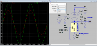
It works if you reduce the current, might get you out of clipping when about 20mW. The output impedance is about 140 ohms, so it can work with 300 ohms hp with some distortion (~5% max.), ~2% @600 ohms load. Distortion is higher @8.5% if cathode resistor 638 ohms is used instead.
Attachments
Last edited:
This is what I ended up going with. 10 volts on the grid and about 60mA through the LM317. Sounds very good and is completely quiet. It doesn't clip anymore either!
An externally hosted image should be here but it was not working when we last tested it.

It is better to put some positive voltage at the G1.
Below a sample with 60 mW out with 0.33 % of THD.
When the current set resistor R6 is 22 ohms (Ia ~58 mA), THD drops to some 0.22 %.
saved the day, nice one Artsalo!
- Status
- This old topic is closed. If you want to reopen this topic, contact a moderator using the "Report Post" button.
- Home
- Amplifiers
- Tubes / Valves
- CCS instead of a resistor in the cathode of a cathode follower?