Morning,
In the mid of a speaker build, so a slight deviation on this request.
i bought a tube amp kit many years ago from a site in china (yep i know).
never really got off the ground as there were hiccups with missing components...
Also the kit was a point to point, and in became too difficult to manage. so i gave it timeout and coming back now.
Not sure if this kit is actually doable, so i am maybe looking for how i can adapt this to another build.
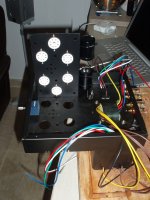
Here are some of the schematics and tube photos. Components seem of good quality so would be a shame to bin them. Let me know if more info is needed.
In the mid of a speaker build, so a slight deviation on this request.
i bought a tube amp kit many years ago from a site in china (yep i know).
never really got off the ground as there were hiccups with missing components...
Also the kit was a point to point, and in became too difficult to manage. so i gave it timeout and coming back now.
Not sure if this kit is actually doable, so i am maybe looking for how i can adapt this to another build.
Here are some of the schematics and tube photos. Components seem of good quality so would be a shame to bin them. Let me know if more info is needed.
Attachments
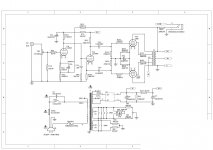
That schematic is an example of tried and well proven voltage amplifier DC coupled to "concertina" phase splitter topology.
If you like, you could easily rework what you have into an "El Cheapo" variant. Any 6V6 family tube will serve, with zero parts changes, as the "finals". Employ triode/UL mode switches, for maximum flexibility. Rhombic shaped pieces of aluminum are used to mount Noval sockets in holes punched for Octal sockets.
Was an integrated bridge rectifier provided by the kit assembler, or were 4 discrete diodes provided?
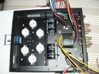
Please upload photos of the chassis and transformers.
If you like, you could easily rework what you have into an "El Cheapo" variant. Any 6V6 family tube will serve, with zero parts changes, as the "finals". Employ triode/UL mode switches, for maximum flexibility. Rhombic shaped pieces of aluminum are used to mount Noval sockets in holes punched for Octal sockets.
Was an integrated bridge rectifier provided by the kit assembler, or were 4 discrete diodes provided?
Please upload photos of the chassis and transformers.
Attachments
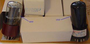
I did some digging and came up with the fact that the Chinese 6N9P is a 6SL7 "equivalent".
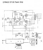
That sort of high RP/low gm triode is a very poor choice for a "concertina" phase splitter that is feeding UL mode "finals". If you want to retain the kit assembler's topology, switch to 6247/12DW7s in the small signal circuitry, along the lines of the Dyna ST-35.
That sort of high RP/low gm triode is a very poor choice for a "concertina" phase splitter that is feeding UL mode "finals". If you want to retain the kit assembler's topology, switch to 6247/12DW7s in the small signal circuitry, along the lines of the Dyna ST-35.
Attachments
I hesitate to give suggestions if you're not comfortable with point to point wiring with that low a component count.
What was the issue with it?
Thanks for the honest feedback.
I think my issues could be due to the confines of the chassis for a first point to point project. I possibily need another type of chassis for the amp, to make it easier to work with.
The schematics look good for a fairly straightforward amp. There are numerous small ways to "improve", but they might not be audible in the end.
You could use a MOSFET for the concertina splitter and ditch an entire tube. This would save space and wiring with no noticeable affect on sound, as well as provide a much better device for the concertina. No heater lift concerns as well.
You could use a MOSFET for the concertina splitter and ditch an entire tube. This would save space and wiring with no noticeable affect on sound, as well as provide a much better device for the concertina. No heater lift concerns as well.
Hey,
here are some photos of the transformers (can't see any markings) and the chassis.
i took everything out of the chassis in the end as i feel that i need some more space to solder it all correctly.
here are some photos of the transformers (can't see any markings) and the chassis.
i took everything out of the chassis in the end as i feel that i need some more space to solder it all correctly.
Attachments
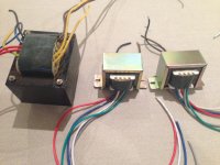
Please provide a photo of an O/P tube along side 1 of the O/P transformers. I have a nagging suspicion that those O/P transformers are undersized.
Compare the size of that "iron" to the excellent Z565 transformer used in the ST-35. The dimensions in the linked drawing are in inches. Multiply by 25.4 to get the size in millimeters.
Compare the size of that "iron" to the excellent Z565 transformer used in the ST-35. The dimensions in the linked drawing are in inches. Multiply by 25.4 to get the size in millimeters.
The combination of 6sl7 to 6v6 output tube is a classic one from the early days. If you check it out many of the 6v6 push pull amps from the 40s and 50s you will see that tube line up is plentiful. It is probably part of the reason why the manufacturer used that combo. Anyway, despite its limitations, it is a good sounding match and should work fine. How much do you have invested? A fairly simple circuit like that, maybe, you should box it up and send it to someone to assemble it for you?
That actually seems very nice, although the OPTs look a little small. I'm still not sure about the phase splitter and the relatively low current of the 6P6P. There's plenty of room in that chassis for components. Did it come with a tag strip or some other way of mounting components?
Invested time more than anything.
No, quite determined to do it myself rather than getting someone to do it for me.
Just need a logical plan of attack! maybe the chassis threw me, when i found i had to drill extra holes for miss ground posts and ill-fitting housings for components.
No tag strip included, just a box of parts and a schematic.
Last edited:
Invested time more than anything.
No, quite determined to do it myself rather than getting someone to do it for me.
Just need a logical plan of attack! maybe the chassis threw me, when i found i had to drill extra holes for miss ground posts and ill-fitting housings for components.No tag strip included, just a box of parts and a schematic.
Ok, so you are going to do it yourself. First you need the proper tools. I use about 4 different long nose/needle nose pliers, other assorted pliers, flat and Phillips head screwdrivers, good wire strippers, flush cutting wire nippers, socket and box end wrenches, and most importantly a good soldering iron. For point to point wiring you need a hot iron at least 60W , I like 100w, with a screwdriver tip about 1/8" wide. You also need a solder sucker to undo soldering mistakes. I also suggest using a Variac as indispensable since it allow you to do preliminary testing or troubleshooting at much lower voltages and less chance of shock hazard.
Generally, i approach it this way, which may not be the way the assembly manual would follow, but rather follows the different circuits.
First thing is to mount transformers, tube sockets, can capacitor, switches, fuse, pilot light, volume control. Next thing , wire up the power transformer primary (tinning stranded wires. This is necessary to prevent the strands from unraveling when you put them through solder lugs, etc. Check on line tutorials about soldering if this is unfamiliar. There is also good and bad technique for routing and fastening wires to the solder lugs, that you should read up on) You should not solder yet as you want to wire up the secondary and do some power tests to make sure your primary is correctly wired and you have voltage to your secondaries. If you have a variac you can put 12vac on the primary and get 10% of unloaded voltages on the secondaries. If all the secondaries show the proper voltages you know your power trans is good, which after confirmation you can solder the primaries. Now, you can hook up your rectifier. If it is tubed double/triple check to make sure all your wiring is correct at the tube socket. If rectifiers are SS make sure they are properly oriented. I am guessing your PS is CRC, capacitor resistor capacitor. Sometimes the R is replaced with an Inductor or choke which makes a PS CLC. Again make sure all the parts and wires are properly connected and polarity for the caps are correct. Also, since the voltages after the rectifier will now be high tension, hot leads need to be insulated with Teflon tubing and carefully routed to prevent shorts. After wiring up the B+ supply you can do another voltage check to verify your progress.
This is a good point to hook up the heater or filament circuit with tightly wound heater wiring and taking care to route the wires in the proper locations. Please check the various articles on how to wire your heaters.
I will stop here and let you reply as to your progress so we know how things are going. I apologize if this is "old hat" to you since you did not describe your expertise at amp building. good luck!
Last edited:
- Status
- This old topic is closed. If you want to reopen this topic, contact a moderator using the "Report Post" button.
- Home
- Amplifiers
- Tubes / Valves
- Tube amp reboot Re: Chinese 6P6P (6V6) Push-Pull Tube Amplifier Kit