May I ask how much total current is drawn from both channels?<snip> I owe everyone here a huge thank you. Especially you, Eli. There is very obvious MOSFET inspiration borrowed from your tweaked RCA design here.
My filter choke is a Triade C-3X, just want to make sure there will be enough current drawn to kick it off.
Thanks!!
-fredv-
Gracias amigo Mosquito ")
I don't remember why I decided to choose castillian names, but I am sticking with it. Potato in English is also spud for slang and a spud amplifier means one tube amplifier (because potatoes are a "tuber" vegetable, I think). So the Papa Rusa is a reference to slang from a scientific classification but translated. Jaja. Maybe not the most obvious, but it sounds good when you say it, too.
Que tengas un lindo domingo.
A month later, another wtf-phone-preamp starts singingThanks, will take a look at your blog!!
It took more time than I expected because I was trying to use my existing parts (new and used), and I am lack of skills and tools
The only parts that I had to purchase was the mosfets. So, it was a bargain project by all means.The most time consuming work was the chassis and played with PSUD2 to figure out the PSU from my unknown Healthkit transformer before the VR resistor.
This evening, I had everything soldered. After triple comparisons of the wiring to the schematic and 4 DMM's connected to various points, I set the variac at 50%, powered it up, and waited for the excitement. No smoke, no smell for 30 seconds, so WTF, turned the variac to 100%. Still no instance except the tube glow, yeah!!! It was late, but I was still anxious to the final check to hook it up to the TT and the amp. The end result, it sang the very first time. Not only that it is very quiet and sounds much better than the opamp based phono-pre, it only costs me $10 out of pocket new money
Thanks for Sodacose and everyone in the discussion!!
Attachments
Glad there's another one in the wild, Fred! Thanks for sharing your build. Any tweaks or tricks you'd care to share?
I have to admit that it was really a "follow the recipe (the excellent blog)" and then tweaked according to what were in my possession.
First trick (not so much a trick, more like a common sense
) is not to use an undersized chassis. The decent size Hammond chassis allowed me to use double adhesive tape to play with various placements with the parts. Still I didn't place the 12AX7 as best as I could. I was too obsessive to put them far from the iron and ended up with some challenge to solder on one side - too close to the side of the chassis.Second tweak was to figure out how to use this Healthkit 54-950 transformer in this build. I measured the ESR and unloaded VAC and used the data to model the PSU in PSUD2. I had to go bridge full wave to get the voltage. Therefore, SS diodes were used. The beauty was I could model the psu according to the parts that I found in my wife's junk box
I used PSUD2 to model the blog's PSU up to the VR resistor at 25ma load. The idea is, if I manage to reach the same "entry" point, I can very much follow the same circuit beyond the VR resistor. I then tweaked the PSUD2 model of my transformer to roughly match the same voltage at the same point (approx. 330VDC). In my live preamp, I measured 24ma consumption from both channels.
Since this transformer has a 14.5 (measured 16.2 unloaded!!) VAC secondary, it was a no brainer to go DC filament supply using a savaged L7812CV which is bolted and isolated to the chassis. This likely contributes a great deal to the quietness of the phono-pre.
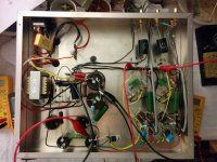
For the RIAA resistors, I essentially series and parallel resistors to get to the values that I wanted. Online parallel resistor calculators were my friends. The RIAA caps are Russian polystyrene (0.01uf) 0.1% and Wima (3300pf) 2%, matched between channels. I wired one 12AX7 per channel; hence, it was easy to visualize whether I wired both channels right or wrong
I had the grounding of each channel converged into one point and then to the 1st cap's ground. That's why there are a lot of black wires.If you look at the 2 new pictures, you will see that none of the filter caps protrudes to the surface. They are all stuck to the chassis using the 3M VHB double adhesive tape which sticks like cement after overnight cure. I can lift the whole chassis by holding the 2 450/220uF caps!!!! This tape is really handy to avoid punching and drilling in certain occasion.
The only little drama that I had was one of the socket pins had solder inside. I didn't know until I had trouble to insert a 12AX7, doh!! The lessen is, if I reuse used sockets, I better check the socket to make sure this will not happen again. The oh $h|t moment was just no joy
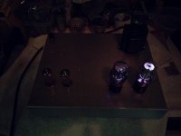
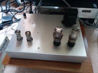
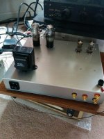
2 more pics from the front and the back, it is kind of some what "empty" .....
Cheers,
Attachments
Hey, I've got all the parts to build this amp, but have a couple questions, as this is my first project of this caliber.
1. Should I try and layout all the parts in the chassis, then wire? Or other way around? I'm struggling with the build order a bit.
2. I'm sure this will make a bit more sense once I've got the transformer in hand, but just to confirm, the heater for the 12ax7 will come from the 2 green leads on the transformer, which are +/- 6.3V, giving me a heater voltage of 12.6V?
3. I sorta see the grounding going on, but the one big thing that confuses me is are all grounds the same? Like is signal ground and power ground the same point? From what I can tell, there are two grounding points in Sodacose's build, one on the right terminal of the motor run cap, and the other one the screw in the chassis to the left of that. Why not ground everything to the chassis?
4. I'm sure there's a way to say this properly, but the resistors between the cathode and ground, do those just serve to reference the cathode to above ground? What does that even mean?
5. One other thing, when testing all of this, I'd like to test the power supply first, especially as I build it. Can I test the power supply with just a multimeter? I'd like to test it after the 5y3gt stage, after the filtering stage, and after the voltage regulation stage?
Sorry, I'm not too solid on my EE and tube theory. I sorta get what's going on, having build a gainclone in the past, but this is just so much more complicated. Are there any good, short, primers on what each component in an amplifier does?
Last edited:
1. Should I try and layout all the parts in the chassis, then wire? Or other way around? I'm struggling with the build order a bit.
Yep, this is how I would do it for sure. Get all your sockets, transformers, and caps mounted first. Then begin the actual wiring process. You'll want to position the 12AX7s further away from the AC inlet, the power transformer, and filtering bits so that it is physically separated from the noisy bits.
2. I'm sure this will make a bit more sense once I've got the transformer in hand, but just to confirm, the heater for the 12ax7 will come from the 2 green leads on the transformer, which are +/- 6.3V, giving me a heater voltage of 12.6V?
The transformer in the BOM has a 6.3V winding with a center tap. You'll need to wire the 12AX7 heaters in parallel (ie one end of the heater tap to pin 9 and the other end to pins 4 and 5). The center tap will be grounded, usually through a simple resistor voltage divider (I think the explanation for this is on my write-up). Heater leads are probably green for the ends and green/yellow for the center tap (again, going by memory).
If this is your first tube project, I highly suggest going with DC heaters. My preamp had AC heaters and it was silent at normal listening levels, but it is not hard to end up with heater noise in such a high gain circuit. Merlin has a really good explanation of DC heaters on his website here: The Valve Wizard
3. I sorta see the grounding going on, but the one big thing that confuses me is are all grounds the same? Like is signal ground and power ground the same point? From what I can tell, there are two grounding points in Sodacose's build, one on the right terminal of the motor run cap, and the other one the screw in the chassis to the left of that. Why not ground everything to the chassis?
All the grounds are connected at only one point (star ground at cap). The TT ground post is also the chassis ground, IIRC. I ran all of the signal grounds to the star ground and all of the power grounds to star ground without mixing "types." Running all of the grounds directly to the chassis would almost guarantee a ground loop and lots of noise.
4. I'm sure there's a way to say this properly, but the resistors between the cathode and ground, do those just serve to reference the cathode to above ground? What does that even mean?
You got it! A tube is biased by creating a voltage difference between grid and cathode. The grid is at ground potential and the cathode is above ground potential by virtue of the current through the cathode resistor (volts is ohms times amps).
Yes you can use a DMM to test this. Just be sure it can handle high voltage. You'll need to test each of these points one at a time and you need to do so safely! Don't move the probes around in a powered up device. Hook the DMM up, power on, observe, power down. The write up includes a discussion of bleeder resistors but be doubly sure all caps are discharged after powering down and before poking around.5. One other thing, when testing all of this, I'd like to test the power supply first, especially as I build it. Can I test the power supply with just a multimeter? I'd like to test it after the 5y3gt stage, after the filtering stage, and after the voltage regulation stage?
So the heater winding has 3 taps, a top, bottom, and center tap. The voltage between the two terminals is 6.3VAC, and the difference between the center tap and each terminal is about 3.15VAC. I have 6.3VAC coming from both terminals, which is the proper heater voltage, that I can then wire in parallel, as wiring in series would cause a voltage drop across all the heaters.
What I don't understand, even after reading the Valve Wizard article, is how referencing the center tap to the heater voltage helps reduce hum. So I have that clean. filtered, and rectified B+ coming out after the rectifier, filter, and regulator section. I would then be putting +32VDC into the center tap of the heater coil. If I understand what this does, this makes the AC voltage float on top of this DC voltage, making it an AC wave between about 29 and 35 volts, which is more than the heater needs, which I know is wrong. What does having that floating voltage actually do??
What I don't understand, even after reading the Valve Wizard article, is how referencing the center tap to the heater voltage helps reduce hum. So I have that clean. filtered, and rectified B+ coming out after the rectifier, filter, and regulator section. I would then be putting +32VDC into the center tap of the heater coil. If I understand what this does, this makes the AC voltage float on top of this DC voltage, making it an AC wave between about 29 and 35 volts, which is more than the heater needs, which I know is wrong. What does having that floating voltage actually do??
What I don't understand, even after reading the Valve Wizard article, is how referencing the center tap to the heater voltage helps reduce hum. So I have that clean. filtered, and rectified B+ coming out after the rectifier, filter, and regulator section. I would then be putting +32VDC into the center tap of the heater coil. If I understand what this does, this makes the AC voltage float on top of this DC voltage, making it an AC wave between about 29 and 35 volts, which is more than the heater needs, which I know is wrong. What does having that floating voltage actually do??
There are interactions between the tube's cathode and heater.
First, there is a maximum DC voltage difference allowed between the heater and cathode. For most common tubes this is 100V DC. So, if the cathode of a tube has a high voltage, for instance as would happen with a cathode follower, then you need to make sure the heater's voltage is 'biased' to a DC voltage that keeps the heater voltage less than 100V different from the cathode voltage.
There is some evidence that having the heater sit on a DC voltage of about +40V from the cathode reduces hum and noise.
A common point of confusion is caused by the use of the word 'ground.' Most will assume that ground has to be at 0 volts DC. This is actually not the case. 'Ground' can be lifted above 0VDC (a positive DC voltage), or it can be a negative DC voltage.
The heater's voltage (or the filament voltage, same thing) is referenced only between the tube's heater pins. It will need a path to 'ground', but that ground can be lifted above 0 volts.
Let's say we have a power supply transformer with a 6.3V AC secondary winding that is center-tapped (written '6.3VCT'). The center tap of that winding can be connected to +40VDC, while the AC supply to the tube's heaters is still 6.3VAC.
The secondary winding's center tap has been 'grounded' to +40VDC. Sorry about the sloppy use of the word 'grounded' -- that's how people often use it. The more correct term would be that the secondary winding center tap has been referenced to +40VDC. However, the heater supply is still 6.3VAC.
This can be done with a DC heater supply too, as long as the 'ground reference' is 'lifted' to +40VDC. The DC heater supply is still a 6VDC supply. It's just referenced to a higher DC voltage, often said to be 'lifted above ground.'
I hope that's not confusing.
--
Yeah, what Rongon said
It should also be added that "grounding" the center tap either to 0V or some DC reference and twisting your heater leads collapses the magnetic field created by the heater current (because it is then flowing in equal but opposite directions). This reduces the chance that 60hz hum will leak into other parts of the circuit. Not having a center tap (or not using a virtual center tap) with AC heaters increases the possibility of heater induced hum.
It should also be added that "grounding" the center tap either to 0V or some DC reference and twisting your heater leads collapses the magnetic field created by the heater current (because it is then flowing in equal but opposite directions). This reduces the chance that 60hz hum will leak into other parts of the circuit. Not having a center tap (or not using a virtual center tap) with AC heaters increases the possibility of heater induced hum.
https://imgur.com/gallery/bjgKz
Here are the guts of my build of the phono preamp posted by Sodacode
I am having some issues with the sound, specifically with the dynamic range, and having rolled off mids and highs...
I followed the schematic and BOM to the letter. The MOSFETS test fine, and it's making sound. I think the dynamic range might be a result of high noise floor from 60Hz hum, which I plan on elevating right now, and probably rectifying and regulating later.
For more records of the troubleshooting, see my reddit thread here:
https://www.reddit.com/r/diytubes/comments/6h022l/tube_preamp_sounds_underwater/
Hi pelayostyle,
Go with the website please. That is easier for me to keep updated with info. One thing I did not include is regulated heaters. I definitely recommend that route to nip any hum in the bud before you build.
Best of luck on your build!
Yup, I have a Pete Millet filament regulator board that I'll be using for the build. I'll post pics here and on r/diytubes (Hello fellow redditor) once I'm done.
- Status
- This old topic is closed. If you want to reopen this topic, contact a moderator using the "Report Post" button.
- Home
- Amplifiers
- Tubes / Valves
- Tube Phono Preamps