


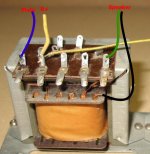
The OPTs are still connected together with the yellow wire. Those solder lugs are were the B+ should go. The most left tab of each OPT should connect to the anode of the EL84. The third tab should remain unused (This part formed a choke used to filter the screen supply of the EL84s - typical design of radios from the 50ies to save an extra choke and to some part compensate some of the anode DC current through the screen current flowing in the opposite direction - those OPTs were really squeezed out to use the smallest possible iron). You should check the resistances of the windings with a standard DVM - the choke part should be lower. On the secondary side, the two thicker wires are the winding for the loudspeaker (4 Ohm impedance). One of these wires is connected to the transformer core metal - open this connection; they used the metal chassis of the radio as return path. The second tab from the right should be the feedback winding (check if it really has a connection to the thicker wires) - leave it unused.
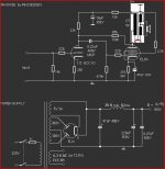
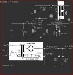
The power transformer in my opinion is not ideal as it only has one secondary winding with about 230 VAC - so it will not give you the desired output voltage of 300 VDC even when used with a silicon rectifier. Furthermore it has no separate winding for the heater of a directly heated rectifier tube - so you can either use silicon rectifier diodes or an indirectly heated rectifier tube in a hybrid configuration with two more silicon diodes.
The power transformer in my opinion is not ideal as it only has one secondary winding with about 230 VAC - so it will not give you the desired output voltage of 300 VDC even when used with a silicon rectifier. Furthermore it has no separate winding for the heater of a directly heated rectifier tube - so you can either use silicon rectifier diodes or an indirectly heated rectifier tube in a hybrid configuration with two more silicon diodes.
The power transformer in my opinion is not ideal as it only has one secondary winding with about 230 VAC - so it will not give you the desired output voltage of 300 VDC even when used with a silicon rectifier. Furthermore it has no separate winding for the heater of a directly heated rectifier tube - so you can either use silicon rectifier diodes or an indirectly heated rectifier tube in a hybrid configuration with two more silicon diodes.
The power trafo in question will yield a B+ rail darned close to 300 V., when bridge rectified with 4X Cree C3D02060F Schottky diodes. The Schottkys are every bit as quiet as a vacuum rectifier.

If the power trafo gives a problem too, it's like this.Soft recovery diodes will do very well.The power trafo in question will yield a B+ rail darned close to 300 V., when bridge rectified with 4X Cree C3D02060F Schottky diodes. The Schottkys are every bit as quiet as a vacuum rectifier.
Mona
Attachments

Yeah i think i need to use another p transformer I dont want to use a seperate filament transformer. I thought there was one in that PT. Oh well...I'm going to build an old school ghetto blaster with tube integrating two very small backloaded horns and an old RCA horn speaker and two 2 inch speakers. The horn speakers will be slightly different because both speaker horns will share the old rca horn using a manifold and high enough up the horn the speaker pressures will not interfere with each other. the tube amp with also sit upon this unit and wired in a cavity in the unit.


View attachment 264-808-tang-band-w2-852sh-specifications-45644.pdf
View attachment 264-808-tang-band-w2-852sh-specifications-45644.pdf
This is exactly as I think it should be. To be sure, please check continuity of the two unused solder lugs - the 3rd from left (assumed screen grid filter choke part of primary) should have connection to #1 and #2 and the 4th from left (assumed feedback winding) should have connection to #5.Is this correct
Please apply power only if these connections are reassured!!
Hey deathrex thanks for your reply. I am going to run 4 ohm speakers for this project as well
Tang Band W2-852SH 2" Shielded Speaker Driver
Tang Band W2-852SH 2" Shielded Speaker Driver
- Status
- This old topic is closed. If you want to reopen this topic, contact a moderator using the "Report Post" button.
- Home
- Amplifiers
- Tubes / Valves
- Need help with OPT for Loewe Opta Apollo Stereo