Didn't see data anywhere on the net, so measured it myself.
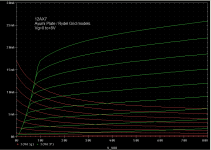
12AX7 Class 2 (Positive Grid Voltage) Operation

I only took 5 points of anode voltage, so it's rather blocky. *The actual curves in the <10V range are quite steep: both in how rapidly plate current rises from zero, and for grid current falling from its peak.
Probably a watt or two of output power would not be unreasonable, and despite being high mu (= lots of grid cross section..?), it looks like the grid is quite 'soft', drawing even less current than a 12AU7 at similar grid and plate voltages. *Looks like "beta" of 3 or so isn't unreasonable.
I'd SWAG a grid power rating of 0.1W should be pretty good for longevity. *12AU7 has the same size cathode, and is rated for 20mA DC, so... there really shouldn't be anything wrong with operating in this region. *And pulses could go much higher (though 'beta' is probably worse at, say, >100mA cathode current).
Possible value of this data:
- Low noise applications, possibly. *The grid current should exhibit partition noise (which could be cascoded back into the plate, at the expense of another active device), but the higher current and transconductance (gm is comparable to a 12AU7!) should result in lower noise otherwise.
- Low voltage effects pedals, buffers. The current is absolutely reasonable for standard applications. *Current gain stinks (it won't make a good follower/buffer/driver on its own), but voltage gain will be good (near 1 for a cathode follower, gm limited for common cathode).
- Zero bias and grounded grid operation. *The average grid resistance is pretty high (around 1kohm at Va ~= 15V?), and gm is still on the low side (2-3mmho) so the cathode input impedance will be modest, perhaps a good match to magnetics (transformers, dynamic mics, moving coil phono pickups).
- RF service, of all things. *As an amplifier, the high mu and low capacitance should give good GG isolation (low s12), high available gain and low output loading (it looks very tetrode-y, without spending extra grids). *As a mixer, the saturation region looks kind of "enhancement mode JFET" like, and may be useful for frequency mixing or analog multiplying.
Tim
12AX7 Class 2 (Positive Grid Voltage) Operation
I only took 5 points of anode voltage, so it's rather blocky. *The actual curves in the <10V range are quite steep: both in how rapidly plate current rises from zero, and for grid current falling from its peak.
Probably a watt or two of output power would not be unreasonable, and despite being high mu (= lots of grid cross section..?), it looks like the grid is quite 'soft', drawing even less current than a 12AU7 at similar grid and plate voltages. *Looks like "beta" of 3 or so isn't unreasonable.
I'd SWAG a grid power rating of 0.1W should be pretty good for longevity. *12AU7 has the same size cathode, and is rated for 20mA DC, so... there really shouldn't be anything wrong with operating in this region. *And pulses could go much higher (though 'beta' is probably worse at, say, >100mA cathode current).
Possible value of this data:
- Low noise applications, possibly. *The grid current should exhibit partition noise (which could be cascoded back into the plate, at the expense of another active device), but the higher current and transconductance (gm is comparable to a 12AU7!) should result in lower noise otherwise.
- Low voltage effects pedals, buffers. The current is absolutely reasonable for standard applications. *Current gain stinks (it won't make a good follower/buffer/driver on its own), but voltage gain will be good (near 1 for a cathode follower, gm limited for common cathode).
- Zero bias and grounded grid operation. *The average grid resistance is pretty high (around 1kohm at Va ~= 15V?), and gm is still on the low side (2-3mmho) so the cathode input impedance will be modest, perhaps a good match to magnetics (transformers, dynamic mics, moving coil phono pickups).
- RF service, of all things. *As an amplifier, the high mu and low capacitance should give good GG isolation (low s12), high available gain and low output loading (it looks very tetrode-y, without spending extra grids). *As a mixer, the saturation region looks kind of "enhancement mode JFET" like, and may be useful for frequency mixing or analog multiplying.
Tim
FWIW, I've got 0.65W from a single 12AX7, common cathode, near-zero bias (a little grid or cathode bias controls zero-crossing linearity, which needs to be balanced otherwise the gain around zero will be too high or too low). Input resistance about 1k ohm, load 4k ohm, supply 150V. (Resistances are per-side, not end-to-end. Which is the load seen / presented by each tube half, since they're pretty well class B with minimal overlap.) Linearity looks good.
Tim
Tim
Comments?
12AX7 model is combination of Ayumi and Rydel/Excem (for Ig). I tried to match your grid current. Ayumi Ip is high, but much better fit in +Vg region than the Rydel 5 parameter model.
12AX7 model is combination of Ayumi and Rydel/Excem (for Ig). I tried to match your grid current. Ayumi Ip is high, but much better fit in +Vg region than the Rydel 5 parameter model.
Code:
.SUBCKT 12AX7AY A G K
EGG   GG   0 VALUE={V(G,K)+0.59836683}
EM1   M1   0 VALUE={(0.0017172334*(MAX(0,(V(A,K))+1e-10)))^-0.2685074}
EM2   M2   0 VALUE={(0.84817287*(MAX(0,(V(GG))+MAX(0,(V(A,K)))/88.413802)+1e-10))^1.7685074}
EP    P    0 VALUE={0.001130216*(MAX(0,(V(GG))+MAX(0,(V(A,K)))/104.24031)+1e-10)^1.5}
EIK   IK   0 VALUE={STP(V(GG))*V(P)+(1-STP(V(GG)))*0.00071211506*V(M1)*V(M2)}
*EIG   IG   0 VALUE={0.001165108*MAX(0,(V(G,K)))^1.5*(MAX(0,(V(G,K)))/(MAX(0,(V(A,K)))+MAX(0,(V(G,K))))*0.8+0.4)}
EIG   IG   0 VALUE={0.000565108*MAX(0,(V(G,K)))^1.5*(MAX(0,(V(G,K)))/(MAX(0,(V(A,K)))+MAX(0,(V(G,K))))*1.2+0.4)}
GIAK  A    K VALUE={MAX(0,(V(IK,IG))-MAX(0,(V(IK,IG))-(0.00058141055*MAX(0,(V(A,K)))^1.5))+1e-10*V(A,K))}
*GIGK  G    K VALUE={V(IG)}
Gg G K VALUE={IF(V(G,K)>0, 220u * ((( 20 +V(A,K))/( 17.3 +V(A,K)))**8.5)*V(G,K)**1.5,0)}
* CAPS
CGA   G    A 1.7p
CGK   G    K 1.6p
CAK   A    K 0.5p
.ENDS
Attachments
Last edited:
- Status
- This old topic is closed. If you want to reopen this topic, contact a moderator using the "Report Post" button.