- -
I found the design had incredible (no hyperbole here) sensitivity to the quality of the screen supply. No screen bypass cap I found did no harm, every one imparted some sort of signature on the sound. I would recommend using an active low impedance regulator to feed the screen grid. - -
I made an RIAA with a 6SJ7 as pentode. The screen was driven by a filtered 120V zener 10 watt and a 10 uF capacitor; Va = 130V; the tube had the cathode to earth (negative Vg). On turning the preamp on there would sometimes be a spark
between the pins of VG2 and cathode/earth. Go think . . . I added a small mica there and the problem dissolved.
Now that is sensitivity to the quality of the screen supply !
I implemented all of your suggestions and using the Statical Regulator for G2 (only one 150V zener just for simulation).
I really want to make a riaa preamp with just one tube, D3a in pentode mode is a good candidate for it. Especially since I have enough of them.
Thanks to everyone.
I really want to make a riaa preamp with just one tube, D3a in pentode mode is a good candidate for it. Especially since I have enough of them.
Thanks to everyone.
Attachments
Rajko,
Shunt cascode is probably what you want to look into with the D3a. I recently tested it with E810F (triode strapped) to build one stage of 50dB gain, completely stable and very quiet. THD is about 0.03% (all H2) for 4Vrms output. Frequency response flat up until 45kHz when loaded with 100K.
Cheers
Ale
<snip>
Thanks Kevin for pointing out your Muscovite Mini thread again. Is it still in service?
All versions scrapped, mainly because I needed the power supply and audio chassis for a prototype strain gauge phono pre-amp which was also scrapped and replaced with the first strain gauge PCB iteration.
The final version - the Muscovite Mini 3 was a good performer and bits and pieces of that design have formed (and will form) the basis of other designs.
<snip>
I really want to make a riaa preamp with just one tube, D3a in pentode mode is a good candidate for it. Especially since I have enough of them.
Thanks to everyone.
Unless you aren't intending to drive any cable at all, a single stage RIAA is a huge, poor performing compromise, (very high output impedance) and gain will be pretty limited.
If what you are really after is a single socket solution you might want to look at the Russian 6F12P, you could use the pentode for the input stage and the triode with a cascode CCS/follower as the output.
Attachments
Had you posted a pdf instead of an ASC I would have, they don't necessarily display correctly in someone else's installation of LTSpice...
Even with the follower the gain concern will remain.
The 6F12P isn't a D3A obviously, but it's not a bad choice for a phono stage even so.
Was there really a reason for the huffy response? I was simply sharing my own experience with you.
Even with the follower the gain concern will remain.
The 6F12P isn't a D3A obviously, but it's not a bad choice for a phono stage even so.
Was there really a reason for the huffy response? I was simply sharing my own experience with you.
No, no.
I was just a little surprised that you did not see the follower in my shematic.
In post No. 31 I have attached the .jpg file of this preamp (without statistical regulator).
Btw, discussion of M. Jones Statistical Regulator can be seen here:
Statistical regulator from VA 4rd edition
I was just a little surprised that you did not see the follower in my shematic.
In post No. 31 I have attached the .jpg file of this preamp (without statistical regulator).
Btw, discussion of M. Jones Statistical Regulator can be seen here:
Statistical regulator from VA 4rd edition
Last edited:
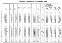
I found this list of equivalent input resistance for some tubes on the Web. Look 1/2 way down the page to the post by Alan Douglas.
Antique Radio Forums • View topic - Vacuum Tube noise figure
6JC6A is quite similar to these tubes below, and costs $1 on the ESRC Dollar Days list:
6688/E180F (R = 330 Ohm)
6EJ7/EF184 (R = 352 Ohm)
6JK6 ( R = 282 Ohm).
12HG7, 12GN7, 12HL7 are cheap 10 Watt frame grid pentode tubes, $3 to $6.
12HG7 (R = 148 Ohm ) is just beating D3a at R = 150 Ohm.
And then there are 5 Watt pentodes on the $1 list, with 20K+ gm frame grids and a spare triode:
6LQ8
6LY8
6KR8
6KV8
Merlinb wrote a good paper. Vogel wrote a good book. Both about Valve (tube) noise in riaa pre-amplifiers.
I recall the concept of hockey stick from Merlin’s paper. As valve current increases from a very low value 1/f noise decreases and total noise decreases. As valve current continues to increase white noise and total noise also increase. Total noise is at a minimum somewhere in there between low and high current.
Keep in mind the audio bandwidth. If we cannot hear it is not noise. Noise beyond the 20KHz BW should be filtered out and not measured.
Even a relatively inexpensive QA401 audio Analyzer can measure this Bandwidth and level of noise.
I have found that you can wire up a tube on a breadboard and vary the valve current with a variable voltage DC supply. As you vary the supply DC voltage/current you can dial in the optimized noise level on the Audio Analyzer.
DT
Noise in Triodes with Particular Reference to
Phono Preamplifiers
MERLIN BLENCOWE
New ballgame:
noise and distortion cancelling amplifiers:
https://ris.utwente.nl/ws/portalfiles/portal/6464856
All N type stages, use triode cascodes for the lower devices. (Fig. 3 gmi and gm2)
Going to want lots of cheap tubes for this, maybe use Mosfets in the cascode tops.
Looks like something for Broskie to write his next 500 blog posts on.
Can add in negative noise and negative distortion now, besides negative hum.
Could be adapted to output stages even, if you can put up with cathode follower outputs. More tubes though. But can be smaller tubes for the cancellation functions. Maybe just use Mosfets for the cancellation stuff. Probably won't sound like tubes in any case without the distortion.
Last edited:
I found this list of equivalent input resistance for some tubes on the Web. Look 1/2 way down the page to the post by Alan Douglas.
Antique Radio Forums • View topic - Vacuum Tube noise figure
Just so happen to have the article mentioned:
Attachments
These measurements are reliable.
I think that they are "calculations" not measurements.
one has to get a bunch of samples and measure as Scott did in his article.
RE: DualTriode
Yes indeed. Looks like the noise cancellation scheme could be done even better too. The Fig. 3 gm2 does not have N Fdbk as shown. But gm2 is assumed to be linear for the cancellation process. By going to a full symmetry, everything can be linearized and noise cancelled together.
Use two high gm pentodes for gmi and gm2. Each gets an N Fdbk resistor from plate to the common grid1's input. (and a cap for DC isolation in each path).
The N Fdbk resistors get adjusted for -just- 1/2 tube noise and distortion correction of the associated tube (usual N Fdbk effect, but weakened here). (so the two tubes will stay at fairly high gain, especially if Gyrator loads are used for each) Each N Fdbk will be be providing 1/2 the correction for the associated tube, but will also be providing the other half of the correction to the other tube. And vise/versa from the other tube. (and the R noise introduced by each N Fdbk resistor will be seen by the opposite tube and corrected in the sum too) So the summed outputs will then fully correct the noise and distortion of the input tubes and N Fdbk resistors.
Now to figure a reasonble way to sum the outputs. Maybe Mosfet followers for each plate with an inverting 1:1 xfmr on one of them to sum the V outputs. OR... possibilities abound.
How about doubling up the whole thing, with two of these correcting gain channels coming from balanced inputs.
Or, put Mosfet cascodes above the pentodes and sum their current outputs, to a Mosfet follower.
Maybe folded Mosfet cascodes for DC convenience.
Hmmm, I seem to recall a solid state audio amplifier (maybe in Wireless World?) that did this double N Fdbk scheme. It seemed redundant to me at the time, but now I see the logic. Brilliant. Should find that schematic. Although a real audio amplifier will need global N Fdbk around the whole thing to get down to PPM distortion. Feedforward/Fdbk is good for chopping out the bulk of the distortion and noise, but would need perfectly matched devices to perform flawlessly.
Harold S. Black 1927
Feed-forward Amplifier
Yes indeed. Looks like the noise cancellation scheme could be done even better too. The Fig. 3 gm2 does not have N Fdbk as shown. But gm2 is assumed to be linear for the cancellation process. By going to a full symmetry, everything can be linearized and noise cancelled together.
Use two high gm pentodes for gmi and gm2. Each gets an N Fdbk resistor from plate to the common grid1's input. (and a cap for DC isolation in each path).
The N Fdbk resistors get adjusted for -just- 1/2 tube noise and distortion correction of the associated tube (usual N Fdbk effect, but weakened here). (so the two tubes will stay at fairly high gain, especially if Gyrator loads are used for each) Each N Fdbk will be be providing 1/2 the correction for the associated tube, but will also be providing the other half of the correction to the other tube. And vise/versa from the other tube. (and the R noise introduced by each N Fdbk resistor will be seen by the opposite tube and corrected in the sum too) So the summed outputs will then fully correct the noise and distortion of the input tubes and N Fdbk resistors.
Now to figure a reasonble way to sum the outputs. Maybe Mosfet followers for each plate with an inverting 1:1 xfmr on one of them to sum the V outputs. OR... possibilities abound.
How about doubling up the whole thing, with two of these correcting gain channels coming from balanced inputs.
Or, put Mosfet cascodes above the pentodes and sum their current outputs, to a Mosfet follower.
Maybe folded Mosfet cascodes for DC convenience.
Hmmm, I seem to recall a solid state audio amplifier (maybe in Wireless World?) that did this double N Fdbk scheme. It seemed redundant to me at the time, but now I see the logic. Brilliant. Should find that schematic. Although a real audio amplifier will need global N Fdbk around the whole thing to get down to PPM distortion. Feedforward/Fdbk is good for chopping out the bulk of the distortion and noise, but would need perfectly matched devices to perform flawlessly.
Last edited:
This is not your father’s feedback.
Hello,
Not to offend the High gm pentode.
The advent of the operational amplifier added tenfold complexity to the notions of feedback and feed forward. The distortion levels of Op-Amps are below the detection levels of state of the art audio analyzers, thrust the need for notch filters or related tricks of magic. Check out the EDN June 20, 1991 page 139 article by Jerald Graeme, Burr-Brown Corp, “Feedback models reduce op-amps circuits to voltage dividers” To this day TI uses some of these methods to test op-amp distortion. The amplifier output is feedback to the op-amp inverting input; the only thing that remains at the op-amp out is the distortion. The signal is completely removed. This output is amplified times 10 and then goes to the audio analyzer.
Take the next logical step; take the distortion only output and input it to the next op-amp inverting input and take some of the original input that feed the first op-amp and also input at the noninverting input of the second op-amp. With some level adjusting the output of the second op-amp is distortion free, (much of the noise is also gone). Next think power amplifiers.
This is not your father’s feedback.
Now back to the original D3a RIAA preamp noise programing.
DT
RE: DualTriode
Yes indeed. Looks like the noise cancellation scheme could be done even better too. The Fig. 3 gm2 does not have N Fdbk as shown. But gm2 is assumed to be linear for the cancellation process. By going to a full symmetry, everything can be linearized and noise cancelled together.
Use two high gm pentodes for gmi and gm2. Each gets an N Fdbk resistor from plate to the common grid1's input. (and a cap for DC isolation in each path).
The N Fdbk resistors get adjusted for -just- 1/2 tube noise and distortion correction of the associated tube (usual N Fdbk effect, but weakened here). (so the two tubes will stay at fairly high gain, especially if Gyrator loads are used for each) Each N Fdbk will be be providing 1/2 the correction for the associated tube, but will also be providing the other half of the correction to the other tube. And vise/versa from the other tube. (and the R noise introduced by each N Fdbk resistor will be seen by the opposite tube and corrected in the sum too) So the summed outputs will then fully correct the noise and distortion of the input tubes and N Fdbk resistors.
Now to figure a reasonble way to sum the outputs. Maybe Mosfet followers for each plate with an inverting 1:1 xfmr on one of them to sum the V outputs. OR... possibilities abound.
How about doubling up the whole thing, with two of these correcting gain channels coming from balanced inputs.
Or, put Mosfet cascodes above the pentodes and sum their current outputs, to a Mosfet follower.
Maybe folded Mosfet cascodes for DC convenience.
Hmmm, I seem to recall a solid state audio amplifier (maybe in Wireless World?) that did this double N Fdbk scheme. It seemed redundant to me at the time, but now I see the logic. Brilliant. Should find that schematic. Although a real audio amplifier will need global N Fdbk around the whole thing to get down to PPM distortion. Feedforward/Fdbk is good for chopping out the bulk of the distortion and noise, but would need perfectly matched devices to perform flawlessly.
Hello,
Not to offend the High gm pentode.
The advent of the operational amplifier added tenfold complexity to the notions of feedback and feed forward. The distortion levels of Op-Amps are below the detection levels of state of the art audio analyzers, thrust the need for notch filters or related tricks of magic. Check out the EDN June 20, 1991 page 139 article by Jerald Graeme, Burr-Brown Corp, “Feedback models reduce op-amps circuits to voltage dividers” To this day TI uses some of these methods to test op-amp distortion. The amplifier output is feedback to the op-amp inverting input; the only thing that remains at the op-amp out is the distortion. The signal is completely removed. This output is amplified times 10 and then goes to the audio analyzer.
Take the next logical step; take the distortion only output and input it to the next op-amp inverting input and take some of the original input that feed the first op-amp and also input at the noninverting input of the second op-amp. With some level adjusting the output of the second op-amp is distortion free, (much of the noise is also gone). Next think power amplifiers.
This is not your father’s feedback.
Now back to the original D3a RIAA preamp noise programing.
DT
Well the -challenge- is to do this low noise amplifier stuff with tubes.
With noise cancellation tech one does not -have- to use the most expensive tubes anymore (which are getting rare as hens teeth fast). It's likely that tube matching is the more important factor now, which becomes possible with say 100x $1 6JC6A or 12HL7 tubes to sort through on the curve tracer. (looking at my two big boxes of those tubes!)
Aside from the low noise issue, the apparent need for only limited N Fdbks to get low distortion also is appealing for general tube power amplifier designs. And balanced input designs appear to fit the model quite well too.
Maybe this scheme is already used in ICs?
There have been a few ICs with magic black boxes (details not shown on the IC schematic typically) that reduce distortion vanishingly. Sure would like to see a review of those ideas.
Hawksford's Error Correction scheme also uses N Fdbk with Feedforward. And since it borders on becoming an oscillator, I'm wondering about this new scheme's stability (symmetrical version) with two N Fdbk loops that intersect.
Wonder if we could laser trim tubes through the glass for perfect matching and stability.
We could also make tube "Op Amps" for summing the noise/dist cancelling signals, although a single Mosfet or high gm tube with local N Fdbk should do that reasonably well (and maintaining isolation between the two inputs).
Last edited:
Wonder if we could laser trim tubes through the glass for perfect matching and stability.
Gonna have to get it out of the glass envelope (poor lens).
Wanna try it ? Regrettably my company's CO2 laser melts in mils not angstroms.
Can you inert the cavity, or does it need a vacuum?
- Status
- This old topic is closed. If you want to reopen this topic, contact a moderator using the "Report Post" button.
- Home
- Amplifiers
- Tubes / Valves
- NEW D3a equivalent on market?