I want to build a powerful (80W or maybe more) tube amplifier and do not want to use semiconductors in it (just because). Since vacuum rectifiers have high internal resistance, the power supply can sag when I turn up the volume. How about using inert gas (not mercury) filled rectifiers like GG1-2/5, which is rated for 2A current and 16V drop? Is there any downside to using gas filled rectifiers as opposed to vacuum ones?
I have built one low power SE amp and have almost completed another, they both use vacuum rectifiers (5C3S - 5U4G). However, SE uses the same average current whether at idle or at full output, so the rectifier resistance doesn't matter, where a PP class AB amp uses more current when playing louder.
I have built one low power SE amp and have almost completed another, they both use vacuum rectifiers (5C3S - 5U4G). However, SE uses the same average current whether at idle or at full output, so the rectifier resistance doesn't matter, where a PP class AB amp uses more current when playing louder.
CHoke input is a mustI want to build a powerful (80W or maybe more) tube amplifier and do not want to use semiconductors in it (just because). Since vacuum rectifiers have high internal resistance, the power supply can sag when I turn up the volume. How about using inert gas (not mercury) filled rectifiers like GG1-2/5, which is rated for 2A current and 16V drop? Is there any downside to using gas filled rectifiers as opposed to vacuum ones?
I have built one low power SE amp and have almost completed another, they both use vacuum rectifiers (5C3S - 5U4G). However, SE uses the same average current whether at idle or at full output, so the rectifier resistance doesn't matter, where a PP class AB amp uses more current when playing louder.
I want to build a powerful (80W or maybe more) tube amplifier and do not want to use semiconductors in it (just because). Since vacuum rectifiers have high internal resistance, the power supply can sag when I turn up the volume. How about using inert gas (not mercury) filled rectifiers like GG1-2/5, which is rated for 2A current and 16V drop? Is there any downside to using gas filled rectifiers as opposed to vacuum ones?
There are a couple of disadvantages: since the operation depends on a glow discharge, that means negative resistance that can lead to high frequency oscillations that could require plate stoppers. The other big disadvantage is gas clean-up, same as for a neon sign.. As the gas pressure drops, the cathode fall increases, eventually overheating and ruining the cathode. This type is specced for 500 hours.
I have built one low power SE amp and have almost completed another, they both use vacuum rectifiers (5C3S - 5U4G). However, SE uses the same average current whether at idle or at full output, so the rectifier resistance doesn't matter, where a PP class AB amp uses more current when playing louder.
I think you're overestimating the problem. Audio amplification isn't like "brick on the key" modes like FM or CRT deflection where you're doing max power continuously while transmitting followed by intervals of listening when the power finals are cutoff. In that case, a PS whose voltage soars when the load drops is very bad.
As for "same average current", that applies to SE and PP regardless of class of operation. The DC plate current meter will stay rock solid when a Class C RF amp is being operated correctly, even if it's plate modulated to produce AM. Indeed, a bouncing DC meter needle means overmodulation and "splatter", or it could be due to a bad impedance mismatch that's causing a higher than normal SWR. The only thing that differs is the magnitude of that average current: from SE and PP and Class A, B, C, D (seldom used in hollow state audio) E or F (never used with hollow state audio)
Audio stays at some low average value with peaks, so sag isn't that much of a problem. Guitar amps often use undersized power supplies and the finals are driven well into clipping, and for that, sag is desirable since this makes for compression and "sustain". You want to keep reproduction amps out of clipping except for the occasional peak that clips the finals. If you avoid blocking distortion, you simply won't hear the occasional clip.
my favorite damper tube: http://www.shinjo.info/frank/sheets/127/6/6CD3.pdf
Thank you for the answers. I was thinking about using 6S33S in PP or using paralleled other tubes (that do not require 1kV plate supply), but then it means high current. I have a couple of 5C8S tubes that are rated for 420mA DC but was worried about the sag and started looking for alternatives, came across mercury rectifiers, but did not like the fact that they are full of mercury.
It turns out that the sag does not happen as much as I thought.
I used choke input filter for the amp I already built and will use one for the amp I am currently building - lower peak current means I can get a bit more current out of the rectifier, well, at least according to the datasheet.
If I need more current than that, then I guess using rectifiers in parallel is still better than the gas discharge tube...
rather the oppositeand low resistance chokes.
Did good change to my system, more detailsI would add Wima DC Link MKP 4 capacitors: no electrolytics!
I have built one low power SE amp and have almost completed another, they both use vacuum rectifiers (5C3S - 5U4G). However, SE uses the same average current whether at idle or at full output, so the rectifier resistance doesn't matter, where a PP class AB amp uses more current when playing louder.
It depends.. SE with a simple transformer/resistor load swings current well above (and bellow) the bias point. Only when the stage is CCS loaded, the current will be same as the bias point and the loadline will be horizontal.
A perfect almost constant current draw stage that uses no CCS is the push pull class A. When the top tube swings more current, the bottom one swings less and vise-versa and the difference is always equal to the bias current, if the tubes are perfectly matched.
Push pull class A stage needs a simpler power supply compared to class AB(B) PP and SE. In the later, you should have a much better filtered PS because of the poor noise rejection and keep it tight and firm, low DCR PS.
My advice is:
-Go for choke input. Remember to damp well the Q-factor of the resulting LC filter. Using PSUD2 will help you a lot.
-Damper diodes like EY500, 6CJ3 will help you. Another alternatives - GZ34 if you will to pay or 866 if you wish to play with mercury.
Last edited:
I want to build a powerful (80W or maybe more) tube amplifier and do not want to use semiconductors in it (just because). Since vacuum rectifiers have high internal resistance, the power supply can sag when I turn up the volume. How about using inert gas (not mercury) filled rectifiers like GG1-2/5, which is rated for 2A current and 16V drop? Is there any downside to using gas filled rectifiers as opposed to vacuum ones?
I have built one low power SE amp and have almost completed another, they both use vacuum rectifiers (5C3S - 5U4G). However, SE uses the same average current whether at idle or at full output, so the rectifier resistance doesn't matter, where a PP class AB amp uses more current when playing louder.
Another vote for damper diode tubes.. I use the 6CJ3 in a few amps. Can't really ask for more than these tubes offer.. Low voltage drops, high PIV, high constant current rating, really long warm-up time. Plus they're cheap as dirt.
They do everything you could need!
It depends.. SE with a simple transformer/resistor load swings current well above (and bellow) the bias point. Only when the stage is CCS loaded, the current will be same as the bias point and the loadline will be horizontal.
While SE swings from (almost) 0 to (almost) twice the idle current, it does that in one cycle - a big enough capacitor can supply the current needed for the "higher than idle" parts and recharge during the "lower than idle" parts.
Class AB should use more average current for higher output (the average current is higher during full power output compared to idle).
However, it turns out I was worried about nothing, the damper diodes have low enough voltage drop to be almost like the gas rectifiers, while the gas rectifiers (if I understand correctly) have shorter life and may have problems with oscillation.
low resistance chokes.
rather the opposite
Obviously "low resistance" is inexact; just as "rather the opposite" is ambiguous.
So, to be more specific, I generally look for high quality chokes of <60r that meet critical inductance for a choke input power supply. Since I usually employ a couple of chokes in series, I try to keep the total DCR under 100r.
I'm not sure what the opposite of that is...
While SE swings from (almost) 0 to (almost) twice the idle current, it does that in one cycle - a big enough capacitor can supply the current needed for the "higher than idle" parts and recharge during the "lower than idle" parts.
This is true. There is still a charge-dischage fluctuation, but it's small compared to a class AB amplifier.
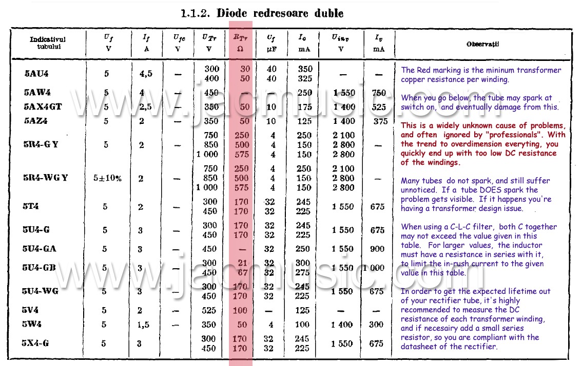
There is an explicit reason why all the most popular rectifier tubes have rather high series resistance: because it is necessary for reliable operation.
Damper diodes are not rated for current surges beyond the peak current required in their intended application.
The surge current due to mains rectification service, especially hot plugging conditions, will destroy the cathode in only a few cycles.
What's the best way to control that current surge? Add series resistance, of course. It's a stupid and wasteful way to go, but so are tubes. Well... that's a rather unkind way to put it, but, I expect few contemporary engineers would've disagreed with that sentiment, either.")
Tim
Damper diodes are not rated for current surges beyond the peak current required in their intended application.
The surge current due to mains rectification service, especially hot plugging conditions, will destroy the cathode in only a few cycles.
What's the best way to control that current surge? Add series resistance, of course. It's a stupid and wasteful way to go, but so are tubes. Well... that's a rather unkind way to put it, but, I expect few contemporary engineers would've disagreed with that sentiment, either.
Tim
The surge current due to mains rectification service, especially hot plugging conditions, will destroy the cathode in only a few cycles.Tim
Shouldn't a choke input filter reduce the power on surge current to more manageable levels?
Damper diodes are not rated for current surges beyond the peak current required in their intended application.
The surge current due to mains rectification service, especially hot plugging conditions, will destroy the cathode in only a few cycles.
Tim
The 6CJ3 is rated for 2.1A peak plate current.. That seems fairly decent to me.
I suppose one could also avoid hot switch-on conditions.
- Status
- This old topic is closed. If you want to reopen this topic, contact a moderator using the "Report Post" button.
- Home
- Amplifiers
- Tubes / Valves
- Gas rectifier vs vacuum rectifier