There is an explicit reason why all the most popular rectifier tubes have rather high series resistance: because it is necessary for reliable operation.
Damper diodes are not rated for current surges beyond the peak current required in their intended application.
The surge current due to mains rectification service, especially hot plugging conditions, will destroy the cathode in only a few cycles.
What's the best way to control that current surge? Add series resistance, of course. It's a stupid and wasteful way to go, but so are tubes. Well... that's a rather unkind way to put it, but, I expect few contemporary engineers would've disagreed with that sentiment, either.
Tim
")
i agree, and in addition Patrick Turner has a good page on power supplies....powertranschokes
Shouldn't a choke input filter reduce the power on surge current to more manageable levels?
Yes, at least for modest values.
The resonant impedance (and therefore, from a step voltage input and I = V/R, the peak current we expect to draw during the LC "hump" response) is given by Z = sqrt(L/C), where L is the inductance, and C is the total capacitance acting against it (which may include the total from subsequent LC sections, if the subsequent L's are relatively small; but power supply network analysis is a topic all its own).
So for 400V input*, 10H and 40uF, we have a resonant impedance of 500 ohms, and expect a peak current of 0.8A.
*At the moment of turn-on, we ignore the ripple on the waveform, and assume it was a step change from zero to whatever the average rectified voltage is. Yes, an average appearing instantaneously is kind of a strange thing, but it works, trust me.
We also expect a voltage overshoot equal to the input step (or 800V total), which isn't very nice. So this should be damped with an ESR similar to the resonant impedance. Capacitor ESR is in the single ohms, so no help there (however, this is relevant to switching supplies, where capacitor ESR is the dominant damping element).
Add up all the ESR in the transformer-rectifier-inductor-capacitor loop. DCR in the windings (primary and secondary), rectifier voltage drop, inductor and capacitor ESR, any added resistance; and leakage inductance in the transformer manifests as ESR. All act to reduce the peak current and peak overshoot... and worsen regulation.
You can also add a lossy C in parallel with the main capacitor, to dampen resonance by parallel action. Typically you'd use ESR = (resonant impedance) and C >= 2.5 x (the C that's already there).
A cap-input filter, on the other hand, charges at a rate potentially limited only by supply resistance and inductance, so can draw tens of amperes (from a low resistance transformer) no problem.
Tim
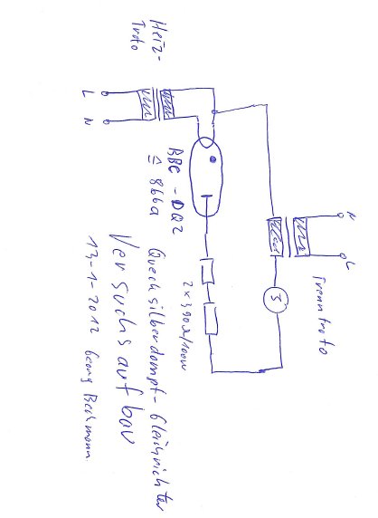
I tried the 866a as well after having used many different normal rectifiers in the outputstage of my 300B-PP. It has completely different resolution and dynamics than anything I heard before. A bit like moving from DVD to Bluray.
While surfing around, I found an article about a professional high-end preamp (aries cerat pondera...>100.000$)...which uses Xenon rectifiers and they make the following claim:
"The power gain is maintained by a single ended-transformer coupled tube stage, using one 814 DHP thoriated tungsten tube. The key to thisstage supreme performance lies to the Negalive Output Impedance Energy Supply. This energy supply has a negative internal resistance throughout the audible spectrum, without the use of feedback or feedforward techniques, so no sonic artifacts are present.
In fact, the negative impedance is compared to a power tube’s transconductance. Where even the best power supply fail in extreme transients needed and sag out, our Negative Output Impedance Energy Supply not only does not sag out, it even contributes to the gain of the preamplifier."
Has anyone a bit more insides on this effect ...which I have not found being pointed out as an advantage of gas/mercury filled rectifiers before ?
Last edited:
I tried the 866a as well after having used many different normal rectifiers in the outputstage of my 300B-PP. It has completely different resolution and dynamics than anything I heard before. A bit like moving from DVD to Bluray.
The next step is to use a silicone rectifier, further improvement in dynamics and resolution due to even lower dynamic resistance.
While surfing around, I found an article about a professional high-end preamp (aries cerat pondera...>100.000$)...which uses Xenon rectifiers and they make the following claim:
Sure, without such claims it would be impossible to sell preamps for $100,000
Wavebourn, I really appreciate reading many of your contributions here at Diyaudio and have a lot of respect of your deep knowledge...and regarding the characteristic of a Xenon rectifier that it got the same voltage drop no matter how much current goes through...SS has the same as you say.
But soundwise I have to disagree. I have build my rectifier section modular, so I can drop in and out SS, tube, gas-filled, whatever. Got the Hexfred, the Cree SiC and ten other SS rectifiers here. No matter which one (I prefer Hexfred from that bunch):
SS gives the macro-dynamics as you say, but introduces as well a SS signature where gas filled seems to be clean (my fully subjective listening experience with which many would immediately disagree).
I went onto Mark Johnson's Quasimodo and built the ring-beller to optimize snubbers...result: you snub as well a fair amount of life out of your system, I would call it loss of transient-response/micro-dynamics. And it became clear to me that SS diodes have a hundred times higher capacitance than tube rectifier and are a much, much bigger bell ringer than tube rectifiers...why some people question the use of snubbers with tube rectifier.
So, I will now extend my experiment with mercury rectifiers and see what a 83 does for my preamp in comparison to an az1/rgn1064 mesh.
I only wanted to know if there is a theory which explains the more on resolution I am getting...and came across the negative impedance characteristic mentioned by the aries cerat guys...
Last edited:
If an amplifier has gain which varies with supply rail voltage (e.g. SET with little or no feedback) and a PSU with significant output impedance (positive or negative) then on and after signal peaks the amplifer gain will vary. This may give the false impression of improved dynamics; in reality it is merely false dynamics. Marketeers can make any amplifier shortcoming sound like a deliberate positive feature.
Last edited:
I've tried everything except a AZ1. Only in one line stage did I detect any difference and that was my Aikido 6SN7/6SN7 in which it seems like a #80 is better than any other rectifier. Tried gas, 5AR4, 5U4's, 5R4's, different damper diode tubes. I noticed that the power supply voltage in most cases changed slightly which is probably the reason for any sonic changes. Also tried SS rectification with a plug in SS rectifier I made and filled with black silicone.
With respect to the $100K manufacturer using a gas rectifier well I guess anyone can make claims about sound and different components. Heck right now we have a LDR audio control maker making claims about increased sonics as a result of his LED connections.
With respect to the $100K manufacturer using a gas rectifier well I guess anyone can make claims about sound and different components. Heck right now we have a LDR audio control maker making claims about increased sonics as a result of his LED connections.
I guess this is why we all are in DIYaudio-country. We ended the journey of commercial BB (bulls.-bingo) where people try to get your hard earned dollar.
At the same time it is about sharing impression to find very individual paths and each milage may vary. Let's stay tolerant and opened-eared. I enjoy to test new ideas and was inspired by the work of Dave Sladge / Hifiheroin and others...they make crazy stuff, but there is a reason for it as I learn now. These guys are not as crazy as it seems in the beginning...my current, completely subjective personal impression.
On the change of Voltage/current topic: We talk about a difference of 15V: 445V to 460V while current is dialed back a bit (fixed bias). But I will test drive the 836/1616 vs. the 866a as well, which give the same voltage drop, but with traditional technology.
Blitz, Please keep up posted as to your results. I personally like the 866AX sound in my PP amps. I'm close to completing a 26 pre-amp with an 80 rectifier because I have a few NOS tubes laying around. I also have some NOS 5Z3's I'm going to try. This is what makes it fun.
By the way: Is there a simple way how to measure the usage status of a mercury tube/ knowing how much they are already used ? I can see that they light differently passing the same current, but not sure if a tube is more spend when she is lighter or dimmer at the same current.
Thanks, that was my inital impression as well...I am only wondering as many people refer to different rating on mercury tubes coming from their testers like Funke Rpg4/3 they offer a 83 with 90% or 95% emission...and I ask my self what this means and how these testers test...which cant be that complicated...i found a white paper of the Neuberger tester, where the Ax50 at least is meantioned as well:
http://www.roehrentest.de/Gleichrichter - Messverfahren nach Neuberger_EN.pdf
http://www.roehrentest.de/Gleichrichter - Messverfahren nach Neuberger_EN.pdf
I can see that they light differently passing the same current, but not sure if a tube is more spend when she is lighter or dimmer at the same current.
I don't think this is much of an indication. The different vintage/make 83s i have all show different amount of mercury and light up in a dramatically different fashion. For some reason, the more mercury, the better appears to be the sound.
Last edited:
- Status
- This old topic is closed. If you want to reopen this topic, contact a moderator using the "Report Post" button.
- Home
- Amplifiers
- Tubes / Valves
- Gas rectifier vs vacuum rectifier