Hi all,
I have some 1625's, 837's and 802's I was going to use for SE. All take the same socket.
These are all transmitting tubes...just wondering if anyone has any experience with the screen voltage limits for these when triode strapped.
I have seen it said (written) that the limit can generally be ignored as long as the plate Voltage never go below the Screen (G2) voltage. (I do not think this is true for all- if any tubes)
I plan on using higher voltage with lower current...I have some 7.8k and 13.5k output xfmers.
Any input is very appreciated
Thanks
Last edited:
The 1625 is internally the same as the 6L6, and you can get pseudotriode data from the spec sheet: 6L6: Frank's.
As for using the other types, not seeing any specs on pseudotriode operation.
As for using the other types, not seeing any specs on pseudotriode operation.
For the 837, from the RCA datasheet, page 8. When the screen and plate are at 200 V, and grid1 is at 0V, then the plate draws 100 mA and the screen 22 mA. The curves look pretty flat at higher plate V, so you can probably assume the screen will draw 22/100 x plate current for higher V and other currents from the plate curves. Then figure the 5 Watt max for the screen dissipation at idle from screen current x screen V.
802 looks about the same.
http://frank.pocnet.net/sheets/049/8/837.pdf
http://frank.pocnet.net/sheets/049/8/802.pdf
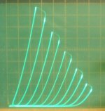
For a cheap and super linear triode, there is the pentode in the 38HE7, available for $1 at ESRC. (they were just $ 0.35 in quantity from Vacuumtubes.net, I got a box of them) The pentode can be operated alone by putting 21V across pins 10 and 12, and should be good for 15 W Pdiss in that configuration. Triode curves below. 50 mA/div Vert., 50 V/div Horiz., 8 V steps on g1. Mu 4.2, Gm 8800 at 60 mA, Rp in triode is about 477 Ohm at 60 mA, 230 mA max. DC. Don't overdo the plate V on these, use the high current to advantage. Screen rated 3.5 Watt. Screen intercepts 1/20 of plate current.
Put 2 in parallel to upgrade a 300B (300B: gm 5500 at 60 mA, Rp 700 Ohm, 100 mA max DC).
802 looks about the same.
http://frank.pocnet.net/sheets/049/8/837.pdf
http://frank.pocnet.net/sheets/049/8/802.pdf
For a cheap and super linear triode, there is the pentode in the 38HE7, available for $1 at ESRC. (they were just $ 0.35 in quantity from Vacuumtubes.net, I got a box of them) The pentode can be operated alone by putting 21V across pins 10 and 12, and should be good for 15 W Pdiss in that configuration. Triode curves below. 50 mA/div Vert., 50 V/div Horiz., 8 V steps on g1. Mu 4.2, Gm 8800 at 60 mA, Rp in triode is about 477 Ohm at 60 mA, 230 mA max. DC. Don't overdo the plate V on these, use the high current to advantage. Screen rated 3.5 Watt. Screen intercepts 1/20 of plate current.
Put 2 in parallel to upgrade a 300B (300B: gm 5500 at 60 mA, Rp 700 Ohm, 100 mA max DC).
Attachments
Last edited:
I checked another point on the 837 screen current curves (page 8). With 200V on screen and plate, but +60V on g1, the screen current is 90 mA and the plate current is 480 mA. So the screen intercept ratio actually decreases slightly with the higher current to 0.19 from (the earlier) 0.22 of plate current.
So, screen dissipation can be safely calc'd as plate V x 0.22 plate current (for triode mode).
Which makes the screen dissipation 0.22 x plate dissipation. Max screen diss of 5 Watts can then be assured if plate diss. stays below 5/0.22 = 22.7 Watts. Since plate dissipation is limited already to 12 Watts, all is well.
One could put a limiting screen stopper resistor in series just to be absolutely safe. 220 Ohms would drop 20V at the 90 mA screen current, so would drop the screen V by 20% when near maximum conduction on a loadline. (probably can't get near that conduction level in triode mode anyway)
802 looks similar.
38HE7, at just 0.05 plate current intercept (has aligned grids), and 3.5 Watt max for the screen grid, would lead to 3.5/0.05 = 70 Watts max plate diss. without melting g2 (in triode mode), which is well above the 15 Watt plate limit. Should be fine, as long as the screen voltage is not high enough to arc over to grid1. Works fine on the curve tracer here up to 1000V for a short term test, but I would not operate it that way. Maybe keep peak plate V to 450V to be safe. (its got plenty of current capability)
Last edited:
Thanks Miles and Smoking-amp.
Do the 837's look like good candidates for an SE triode mode amp? The pentode lines look linear to me for both 837's and 802's.
Have either of you or anyone had good luck with 807's or 1625's in SE? I read they weren't good in this role...even for background music... my curiosity will probably have me build it anyway...but other opinions are good.
I've only used the 1625, and that was in pentode mode for an Amateur Radio xmtter a long time ago. My 1st question would be whether you can plot a useful power output load line for the 837 or 802, without having to resort to positive grid 1. I wouldn't normally consider zero bias tubes, especially for low Watts out. Then an Xmit type HV power supply and a plate cap would definitely kill the deal.
Last edited:
rcollege,
You sent me a pm asking me to join in.
I have played with these tubs minus the 802. I also tried 307a’s and 6BQ6’s.
The large coke bottle shape is nice. The top cap adds to the look as well.
The plates are ample for the rated power. Keep in mind hard work may shorten life.
The fun I had with these tubes was as a headphone amplifier. I ran them at low plate voltage and higher current in an effort to minimize plate resistance and output impedance.
All these SET headphone amplifiers were nice however none of them were the Holy Grail. The music is in your head between your ears. There are no delayed reflections, no interaction with the space.
DT
Thank you for your response DualTriode.
It seems that after reading the responses, I may have to put these tubes away for a bit.
I have low funds, and little room...and small OPT's...along with small 90dB speakers.
I need power, but I don't want to use tons of current, as it is easier/ smaller to produce high voltage than high current. It allows for smaller iron.
I may just find tubes that can handle higher voltages, JJ KT88 go up to 800V...with using only 40mA I can get 4.5W with a 7.8K OPT...good distortion figures as well.
I could easily build a PP, but I love the sound that I get from SE.
I have a Dynaco ST35... I see no reason for another PP amp.
I'll let you all know.
Thanks
The following information is roughly translated from a Japanese website, it basically says that we should forget about fearing screen grid meltdown when the multi-grid tubes are triode connected, run them not at the maximum screen grid voltage but at the maximum anode voltage, in fact, even that can be exceeded - as long as the Pda is observed, there is no problem at all. The tradeoff are higher required grid bias voltage/drive and somewhat higher RL.
I am also planning to produce 837,1624,307A, 12E1 single-ended tube amp. In addition to 1624 using the pentode connection, other are used triode connected.But we have been unable to determine the 837 (rk44) anode consumption and can not determine the operating point. You have information 837 can determine the maximum anode power it? I can only conservative tentative in 16w (anode + G2 + G3).
802, significantly less than the 837 anode power.
1625 same as 807.
802, significantly less than the 837 anode power.
1625 same as 807.
Last edited:
Good question! I think 16W is a good starting point, but the tube should be able to handle more, looking forward to see how far you can push it...You have information 837 can determine the maximum anode power it? I can only conservative tentative in 16w (anode + G2 + G3).
")
Good question! I think 16W is a good starting point, but the tube should be able to handle more, looking forward to see how far you can push it...
16w time (anode + G2 + G3), the same curves 837 and 801. Output power up to 5.2w.It has been very valuable. 837 both direct thermal, thermal side advantage is a rare good tubes.
16w time (anode + G2 + G3), the same curves 837 and 801. Output power up to 5.2w.It has been very valuable. 837 both direct thermal, thermal side advantage is a rare good tubes.
The 837 has the same curves as the 801?
Now I have to build the amp.
I just got some 15lb power transformers that I'm going to try out as output transformers. I think the core is large enough not to saturate at 50mA. The core surrounded by the windings is about 5 x 3x 3 inches thick.
Plus the primary DC resistance is only 11 ohms. Secondary is 4.3 ohms. The question now will be inductance and calculating the impedance... I believe it is 3.2k
Output transformer and power transformer are required to make their own satisfaction. I do not believe what he bought transformer will marvel.
Yes, 837 connected to the transistor, the curve is similar to 801.
Output transformer and power transformer are required to make their own satisfaction. I do not believe what he bought transformer will marvel.
Yes, 837 connected to the transistor, the curve is similar to 801.
I understand that there is a difference between output and power transformers. I am amazed at the sound I have gotten from some power transformers. The main thing I am trying to do is see how larger diameter wire will affect the sound...mainly high frequency response. Also, the size should be enough to prevent saturation.
One other thing...it is wound on a split bobbin...one side is the primary...the other is the secondaries. This should also have an effect.
Where did you hook up the transistor to the 837? Did the transistor act as a current source?
Where did you hook up the transistor to the 837? Did the transistor act as a current source?
I think he meant triode, not transistor.
I think he meant triode, not transistor.
I'm sure you are right.
Now I feel silly for not figuring that out... I swear I'm usually smart enough to figure these things out... sometimes....
I Tried and listened to the 802, 837 & 1625
I built my mom an amp that can use the 802, 837 and 1625's- all in triode.
The amp has a B+ around 516vdc.
I will open another thread about this amp, but the sound of these tubes are good and worth the effort.
The tube that stands out, surprisingly, is the 802. I'm not sure how much power it is putting out, but it does it clearly, transparent with detail, timbre and balanced sound. I won't go into more adjectives.
However, I also increased the cathode resistor from 1.5k to 2k to keep the amp from pulling too much current for the tubes. This may have had a large impact on the sound as well.
The Amp is named Misty...
The 1625 is identical to the 807 except that the 1625 has a 12.6V 0.45A filament.
The screen grid max rating is 300V.
The 837 screen grid max rating is only 200V.
The 802 will need to be operated in pentode mode to get any power.
For any of these tubes in pentode mode, your output transformer will have to have Lots of primary inductance (or you will not get any bass).
in general, Inductance is easier to obtain with push pull transformers than with single ended transformers. That is why some chose to use parafeed single ended, but then you need an extra coupling cap, and a plate choke with lots of inductance.
Using the tubes in Triode wired mode, the screen will follow the plate (a 100 Ohm resistor from plate to screen is suggested).
You will get more power if you use the 1625 in pentode mode, but you will almost certainly need to use negative feedback (for distortion reduction, and to have a decent damping factor). Your
high impedance output transformers will work here, as long as you can make the amp stable with negative feedback. Negative feed back is more complex.
You might use a pair of 1625s in pentode mode push pull, or triode wired push pull.
Push pull is more complex.
The below is a sample of how you might use the 1625 in SE triode mode.
This is less complex, but has lower power.
Given a 1625 output tube in a single ended amp with 300V on the plate and screen, the plate and screen will swing to as high as 600V at cutoff. That will not damage the tube because the plate and screen current are zero, and the dissipation is zero. But at cutoff the audio will be clipped. That is at the limit of the circuit. The solution is to turn the volume down (just apply less signal to the control grid to keep it out of clipping).
There will be a small voltage drop across the single ended transformer primary.
For example, a 60mA plate + screen current and a 300 Ohm primary DCR will drop 18V.
That means the B+ can be 300 + 18V = 318V.
If you use cathode self bias, the bias might be 22V.
In that case the B+ can be 300 + 18 + 22V = 340V.
The output transformer might be from 3200 to 4800 Ohm primary impedance.
The 3200 ohm transformer might give about 2W output, and have a damping factor of about 2.
The 4800 Ohm transformer might give about 1.8W output, and have a damping factor of about 3. There will be a little less power because of the transformer loss, and the damping factor will be a little lower due to the transformer loss too.
You might use RC coupling from the driver tube. If the plate swings from say 180 to 224V that could work. In any case, the driver should be capable of a linear swing to the 1625 control grid from +22V to -22V. A swing of more than that will cause clipping if the 1625 bias is 22V.
I will have to set up the oscilloscope out and do some tests.
I'm using a 14kohm output transformer. Also, I am running a higher voltage...500 for B+ in triode mode. Less current from the power tube is required to drive the speakers. This allows for decent power with lower odd order distortion.
Higher voltage Running less current means a smaller power transformer, the option for a voltage doubler...as I just used, smaller chokes, smaller filtering capacitors and reservoir capacitors. Smaller output transformers with smaller gaps.
I found that using a high impedance transformer gives better, tighter bass because there is ample current due to the turns ratio.
Of course, it also results in loss of volume..
Just my own observations
- Status
- This old topic is closed. If you want to reopen this topic, contact a moderator using the "Report Post" button.
- Home
- Amplifiers
- Tubes / Valves
- Maximum Screen Voltage for Triode Strapped 1625 or 837