Point to Point Wiring
Hello Costis,
Either one will suffice. What I am actually doing is combining a P.S. consisting of a P.T 350-0-350 and a choke input clcl delivering a B+ of 300vdc with approx support of 90ma load. This in turn will hookup to a akidido Octal line stage preamp using 6sl7 and 6sn7. I,m old school and tend not to use pcb's.
I have built many Heathkit components but then again everything was laid out on paper. I am more concerned in reference to placing components in chassis where there is little ac or signal interference, placement of tubes,resistors,capacitors etc etc.There are a lot of Broskie boards out there but none that I see in a point to point setup. Any photos or drawings would be helpful. Thanks again.
Joe
I'm old school too
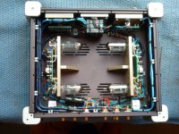
I've built a few Aikidos too, both PCB and P to P. They are such a simple circuit it's not hard to lay them out. I've used Partsconnexion tag boards (More Information Page) actually one cut in half (see attached picture). The picture shown is of a dual 6CG7 (essentially a 9 pin 6SN7) line stage with separate power supply. The sound is a bit old school in the bass (a bit warm and "slow"). I might rebuild it with 6DJ8s. Will using a 6SL7 in the first stage give you more gain than you want for a line stage? 6SN7s in both positions might give you all the gain you need.
Cheers, Steve
Attachments
Oh. you want a layout. I don't think you will find that pre-drawn.
What you should do is get a few of these and make up your own. I have been using them for years, you can solder and unsolder on them as much as you like, they are indestructible. A lot better than the dinky boards you find in point-to-point guitar amps. When you are happy, just screw them in your chassis, they have bronze threads.
If you do not know how to do layout, you really should get this fine book. Covers layout and a lot more. Or ask the helpful folks in here.
Hope I helped.
Costis thanks for that link, I just bought a bunch..Merry Christmas!
To you and your family, too!
You gonna enjoy them a lot!Point To Point
Costis,will follow up on book by Morgan Jones and thanks again.
Steve, will do some tube rolling after circuit is built to compare using 6sl7 v 6sn7 to compare gain.And thanks for the photo.
BTW is there a guide or tutorial on understanding the use of PSUD2?
Have a Merry Christmas!!!!!
Joe
Costis,will follow up on book by Morgan Jones and thanks again.
Steve, will do some tube rolling after circuit is built to compare using 6sl7 v 6sn7 to compare gain.And thanks for the photo.
BTW is there a guide or tutorial on understanding the use of PSUD2?
Have a Merry Christmas!!!!!
Joe
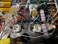
It's not an Aikido, but it is layed out Point to point, and it is very very quiet . you could replicate the construction style using octal sockets, and for as many tubes as you need.
The "Members Only" Riaa Tube preamp. (Photos 8-4-2019) | Audiokarma Home Audio Stereo Discussion Forums
I didn't use anything super fancy to build it, just imagination and the local hardware store . if you can get a large sheet or tablet of graphing paper that helps to get a physical layout drawn up, and can even be used to transfer drill points. Point to Point wiring is a really beautiful art form, which I personally love looking at. Thank you for taking the time to keep the art alive, and to do this the right way. Keep up the good work .
Last edited:
I've built an Aikido headphones amp with point to point wiring. Photos can be found in this (and older) posts on my site:
OTL800: Headphones Amp klaar
Greetings,
Robert
OTL800: Headphones Amp klaar
Greetings,
Robert
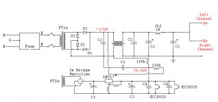
Here is a fairly simple, proven design by a pro, that lends itself to point to point wiring.
DIY ECC802S (12AU7 / ECC82) Vacuum Tube SRPP Preamplifier
DIY ECC802S (12AU7 / ECC82) Vacuum Tube SRPP Preamplifier
Here's my chosen layout for "Aikido" point to point...
Kinda looks more like a "Ratsnest" preamp to me.
jeff
for better PSRR:
Attachments
Nice work Steve in post #4.
What's that device between C1/2 disco? A bog standard 1/1 tfmr or some sort of common mode choke? The schematic would have been clearer if the second C1, the 100k and the 220k resistor had been better placed. What is their purpose, apart from dropping HT/B+ for a V reference for the HTR, some sort of phase compensation?
Andy.
Cags, have a look at this
It's not an Aikido but the methodology might appeal to you.
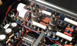
The tube sockets mount on top and their pins connect to the turrets from below. In the case of grid stoppers they are below connected from the socket pin to a turret. Small holes can be drilled for parts mounted on top but connected on the bottom. Making a big hole for the socket is a bit of work but a drill and Dremel tool does it. Of course you need longish standoffs so the tube pins will clear the chassis bottom with lots of room to spare.
Just get a turret board, the schematic and your parts (make a paper trace of the board if you wish) and experiment with component positions.
The left side of the picture below has power supply components mounted on a turret board as well. A few holes were drilled for the caps and they were wired to the under side of the turrets.
Good luck, give it a go!
Steve
It's not an Aikido but the methodology might appeal to you.
The tube sockets mount on top and their pins connect to the turrets from below. In the case of grid stoppers they are below connected from the socket pin to a turret. Small holes can be drilled for parts mounted on top but connected on the bottom. Making a big hole for the socket is a bit of work but a drill and Dremel tool does it. Of course you need longish standoffs so the tube pins will clear the chassis bottom with lots of room to spare.
Just get a turret board, the schematic and your parts (make a paper trace of the board if you wish) and experiment with component positions.
The left side of the picture below has power supply components mounted on a turret board as well. A few holes were drilled for the caps and they were wired to the under side of the turrets.
Good luck, give it a go!
Steve
Attachments
I've built an Aikido headphones amp with point to point wiring. Photos can be found in this (and older) posts on my site:
OTL800: Headphones Amp klaar
Greetings,
Robert
Netjes gedaan Robert!! Je site bezocht en je uitstekende
soldeerwerk bewonderd.
Very nice job EL504! Visited your website and enjoyed
your excellent wiring job.
Where did you purchase those chassis parts?
More nice work Steve, I like that idea. I used a similar idea where I made a turret tag board but used single sided copper clad board, and cut out tracks or traces using a Dremmel. This gives the advantage of a tag board, P - P wiring and PCB all in one.
BTW, did you make up those turret tag boards yourself? If not where did you get them and if so what is the black substrate/material used for the board
Andy.?
BTW, did you make up those turret tag boards yourself? If not where did you get them and if so what is the black substrate/material used for the board
Andy.?
Andy,
Thanks. I've used these a few times. They are FR4 (glass fiber and resin) 300mm long. Got them on eBay. A bit pricey. Available in three colours. I cut them to length with a cheap hand saw in a wooden mitre box.
Steve
300*60*2mm DIY FR4 Audio Board Guitar Turret Board Tinned Copper | eBay
Thanks. I've used these a few times. They are FR4 (glass fiber and resin) 300mm long. Got them on eBay. A bit pricey. Available in three colours. I cut them to length with a cheap hand saw in a wooden mitre box.
Steve
300*60*2mm DIY FR4 Audio Board Guitar Turret Board Tinned Copper | eBay
- Status
- This old topic is closed. If you want to reopen this topic, contact a moderator using the "Report Post" button.
- Home
- Amplifiers
- Tubes / Valves
- Point to Point Wiring Tube Preamp