hello,
i'm a new member in here as i found this thread at google, maybe i can throw in my problem with my D90, hoping that someone might give some insights.
My D90 is almost 2 yrs, bought it used and no idea of the tubes life and this is my first tube amp. 2 wks ago, i had this humming noise coming from my speaker and came out that it's the D90 not my tube preamp causing the hum. Read some blogs that most of hum noise were caused by faulty power tubes 6550. As this 6550 is quite expensive, so i tried to swap firstly the input tubes which didn't solve the issue.
I did a voltage test, i'm getting the -125 and 310V but the 410V line coming out from the bridge rectifier is dropping to 325V. i tried to put a new 6550 on the V19 thought that it might be faulty and it's the controlling the 410V but still didn't solve the issue.
Checked the bridge rectifier by diode test, seems OK. getting a 0.6V bias voltage at power off. Now, i've runned out of options before i buy a new 6550, woudl liek to ask anyone of you for any recommendation or if you encounter same issue before and how did you resolve the issue.
Thanks and appreciate all your inputs.
Arnold
i have not seen schematics, but if you can post one, that will be better..
b+ drops big as the output bias increased...
if you have a "kill-a-watt" meter on hand, it will give you an idea of how muhc your amp is pulling at start up and when all the tubes have warmed up, a quick check on the service manual will tell you what your up against...

b+ drops big as the output bias increased...
if you have a "kill-a-watt" meter on hand, it will give you an idea of how muhc your amp is pulling at start up and when all the tubes have warmed up, a quick check on the service manual will tell you what your up against...
AR likes complicated circuits in my opinion...
my experience is that even simpler topologies like the mullard 5-20 or a concertina amp can really sound nice....
if that was my amp i will rebuild it to a much simpler amp...
FWIW, i used to repair pc motherboards with bloated caps in the past, what i did was yank out the bloated caps,
i do not recommend this however....
Even a Williamson setup would be great choice, possibly with addition of
A cathode follower to each of the driver tubes, driving a P-P parallel output.
Attachments
Thanks for the hints about the varnish. I will make sure that it's not water based.
As for the bias, my problem is that the Voltage drop I measure over the resistor is varying rapidly. It jumps up and down by as much as 5 or 6 mV. (Which effectively is 5 to 6 ma, as the resistor is 1Ohm.)
This happens on all 8 valves, so there must be a common source. (Which isn't the supply Voltages. Those are stable.)
Let me try to attach the schematics to this message.
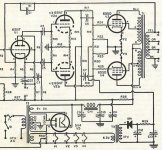
that tube is a shunt current regulator triode, it is showing by the readings that your tubes are drawing a lot of current, i do not think that is the problem unless you can test those tubes on a tube tester....
AR seems to want to make the idle currents more close to full power bias currents......
This is a pretty old amplifier and the electrolytics may need replacement. (A ripple measurement would tell the tale, but do you have the experience to do that safely?) Under load that 410V supply should be pretty close to the schematic value. (I used to service ARC amps until 25 or so years ago, but am not familiar with anything recent.) If I am not mistaken this amplifier was manufactured from 1980 - 1985 so would be at least 35 years old.
You need at least 80V across the 6550 for it to regulate correctly, the plate supply should at all times be above 400V at nominal line voltage.
Check the bias supply, should be -125V approximately. Idle current is about 75mA per output tube.
You need at least 80V across the 6550 for it to regulate correctly, the plate supply should at all times be above 400V at nominal line voltage.
Check the bias supply, should be -125V approximately. Idle current is about 75mA per output tube.
that tube is a shunt current regulator triode, it is showing by the readings that your tubes are drawing a lot of current, i do not think that is the problem unless you can test those tubes on a tube tester....
AR seems to want to make the idle currents more close to full power bias currents......
Need to have another look, it's not a shunt regulator at all. It is in fact a cathode follower for a big stack of zener diodes.
WRT bias currents that's not my experience at all, one of the big problems with the higher power amps is the extremely high plate voltages and modern 6550/KT88 which malfunction as a result. The D90 should not have this problem with its comparatively low plate voltage.

Hi Kevin,
i have checked the bias of the tubes and all are pretty close to 75mA.
i can get the -125V and 310V line stable but not that 410V coming from the output tube V19.
i'm not convinced that the hum noise is caused by power tubes, even i swap power tubes still there's hum noise on both channels if only 1 channel have issue then i would say, it's one of the 6550 though i cannot tell the tubes are bad as i don't have a 6550 tube tester but nonetheless i can set correct bias.
Question, if tubes can be biased can it be bad or starting to fail? only test i can do is the short test of cathode heater of pin 2 & 7 by DMM
I will try to scope the capacitors of V19, that 10uf to see if any ripple on it, good thing i have a Tektronix scope. and i started looking for this 10uF 450V but seems difficult to find, tried Parts connection and Parts express, any idea where to get this tall 10uF 450V?
thanks,
arnold
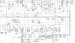
The 410V is the main B+ voltage , just rectified and filtered with those paralleled electrolytics from the transformer . Then the 310V rail is coming from V19 wich is a simple series voltage regulator . If the input (410V) is only 325V then the regulation is not good and could explain the hum . This is the supply voltage for the small signal tubes .
If 410V rail is too low you should check the alternating voltage before the bridge ~310 Vac . Then try to pull out the output tubes and see if the voltage goes up .
If 410V rail is too low you should check the alternating voltage before the bridge ~310 Vac . Then try to pull out the output tubes and see if the voltage goes up .
Last edited:
just scoped that 410V line and seeing a trapezoid like waveform with gittery edge, i believe this line should be pure DC, right?
and measured the voltage before the bridge rectifier, one side is 162V.
is it safe to pull out that tube V19? remove v19 while it's powered on or before powering on?
also, i'm a bit confused 410V coming out from rectifier and 310V from V19.
schematic show 310V before rectifier or transformer output and i measured 162V on each side. isn't rectifier just changing the waveform from ac to pulsating dc but not the voltage level then those power caps remove or filtered those pulses to make it DC then V19 should be the one amplifying it to 410v?
Attachments
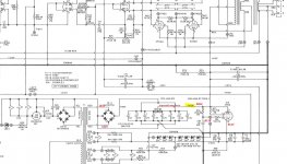
on schematic, it is written (not my writting) 310V on transformer output that is why i got confused if 410V is the main B+
yah, this is my first tube amp to deal with but not new on repairing my own solid state amplifier so i don't mind to learn basic in tubes.
i guess, i just have to deal with my own issue then if some people are judgemental instead of helping..thanks anyways
yah, this is my first tube amp to deal with but not new on repairing my own solid state amplifier so i don't mind to learn basic in tubes.
i guess, i just have to deal with my own issue then if some people are judgemental instead of helping..thanks anyways
Thats just a coincidence that the transformer secondary should be 310V AC for 410V DC rectified and the DC voltage regulated after V19 is 310V DC .
The alternating voltage must be measured across the secondary winding .
410V should be obvious DC voltage with a bit of ripple . If not check the connections with those paralled electrolytics , I doubt that all of them have dried out , eventually check them .
The alternating voltage must be measured across the secondary winding .
410V should be obvious DC voltage with a bit of ripple . If not check the connections with those paralled electrolytics , I doubt that all of them have dried out , eventually check them .
Last edited:
replace ecaps with new ones on the psu as much as you can....
20 years under heat and the caps could have dried out....who knows?
get yourself an esr tester to check each caps before replacing them...
get your tubes tested on a tube tester maybe to find out how much life is left...
20 years under heat and the caps could have dried out....who knows?
get yourself an esr tester to check each caps before replacing them...
get your tubes tested on a tube tester maybe to find out how much life is left...
coincidence that i got confused on the voltage written on schematic on the secondary voltage and after the rectifier.
but waveform captured shows, power caps are no longer doing it's job, still getting AC.
hard to find ESR meter in my area, replacing these caps would be very painful. it has 3 big support pins soldered to the ground plane, i have only manual desoldering pump, it would be easy using a heated solder sucker.
and finding the same cap would be way too expensive if i can find.
- Status
- This old topic is closed. If you want to reopen this topic, contact a moderator using the "Report Post" button.
- Home
- Amplifiers
- Tubes / Valves
- Audio Research D90... a HOT, buzzing amplifier