I've been building amps & other electronics for more than 70 yrs. But never my day job. I will be 86 in a couple of wks. But other than failures for one reason or another I've never experienced any serious problems with the linear components, Ls, Cs & Rs.
Congratulations on 70yrs in electronics!
I know most of us would like to upload your wealth of knowledge.
Yes, of course - 560K. thanks for pointing that out.
Well, I've been neglecting the 26 for a while because I couldn't get it to sound as good as the other DHTs I was using, but this incarnation is impressive. I'd be interested in some feedback from anyone else that can build it.
Hi Andy, Have you reached a definitive conclusion on the sound of diode bias? I'm putting together a 26 pre (doing power supply at the moment). I have 30 diodes and a few types of resistors on hand. I'm considering trying both with the ability switch between the two (powered down of course). I have a set of Ale's gyrator boards stuffed and Ron's raw plus filament boards ready to go.
Best Regards,
Mark
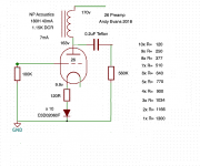
Recently I've been experimenting with the old telecom German DHTs: Aa and Ba. These are lovely beauties but somehow challenging to implement effectively due to their hum succeptibility and very low anode current and high anode resistance. In this case, the hybrid mu-topology plus an output source follower proves to be ideal combination. Distortion is extremely low as well as flat frequency response up to 100kHz.
More importantly, the sound is great. Both have the detail and clarity I look for on these DHTs. The instrument timbre is there as well as the dynamics.
Also made some measurements showing that the use of SiC diodes as filament bias work very well. The Ba uses 6 and the Aa only 2. I see no detriment of the harmonic content as measured and listened to. I will keep this bias arrangement for now, it's very nice to my ears.
You can read more about these 2 preamps and look at diagrams and measurements here:
Aa Preamp: http://www.bartola.co.uk/valves/2018/09/07/aa-dht-preamp-part-i/
Ba preamp: http://www.bartola.co.uk/valves/2018/08/26/ba-dht-preamp-build/
Now I need to make a decision on which stage will go to ETF in November!
Cheers,
Ale
It all just gets more and more interesting!
I've been lazy and have just been listening to my 26 stage with SIC diode bias (not filament bias) for a few weeks. It sounded good right from the start. I keep meaning to change some of the diodes for a resistor, and then do the same in filament bias. I'll get round to it in the end!
I also want to try a 3a5 with SIC diode bias as a first stage for a PP amp. I had an idea something like this.
Attachments
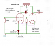
Hmm, doesn't look quite right. I'd like to see independent regulators and a CCS tail with means to adjust currents through the core.It all just gets more and more interesting!
I've been lazy and have just been listening to my 26 stage with SIC diode bias (not filament bias) for a few weeks. It sounded good right from the start. I keep meaning to change some of the diodes for a resistor, and then do the same in filament bias. I'll get round to it in the end!
I also want to try a 3a5 with SIC diode bias as a first stage for a PP amp. I had an idea something like this.
Curiosity led me to tweak the 26 preamp I've been using and enjoying for a couple of weeks. With the SIC diodes it turned out much better than I expected. Here's my latest version where I've run the 26 at 7ma. Not quite max dissipation but close. I put a 120R resistor at the top of the string of diodes in the hope it would add a little useful feedback. Whatever its doing, the whole thing works very nicely. I'm really pleased with this. Clarity is really up a level, as we witnessed when Ale presented his 01A with SIC bias for our recent preamp shootout, which is on his blog. This whole SIC diode bias idea is a step forward in my view. This is my best preamp to date, I believe.
Attachments
Last edited:
One regulator can work. You can add a balance pot between filaments and SiC array for bias adjustment. That will compensate mismatch of valves and filaments
I just can't see how the pot will work with one regulator and a common CT filament supplying both triodes within the envelope.
Last edited:
How many volts do you need them to swing? Mind you the 3a5 is an excellent valve for low level signal and not to swing many volts. I measured about 0.2% for 10Vrms on a single ended driver test. It may sound really good though.
Not obviuos where the 10 mV was measured, at the input or the output? How much gain did the stage have? How did you measure D%?
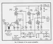
Just curious. These preamps seem very different than what I recall, those required to amplify & properly shape the response curve of a magnetic pickup on vinyl. For that 12AX7 was the dominant choice. 12AY7 is purpose built for lower noise. EF86/Z729 would also work. And for very low noise, cascode was used, often done with high Gm RF triodes such as the 6BQ7/6BK7 family.with DC on the heaters.
This thread seems to be describing something for a very different requirement.
")
Attachments
It all just gets more and more interesting!
I've been lazy and have just been listening to my 26 stage with SIC diode bias (not filament bias) for a few weeks. It sounded good right from the start. I keep meaning to change some of the diodes for a resistor, and then do the same in filament bias. I'll get round to it in the end!
I also want to try a 3a5 with SIC diode bias as a first stage for a PP amp. I had an idea something like this.
The front end of a PP amp if it were differential wud normally have a common impedance at the point where the cathodes are brought together. That is how balance & common mode rejection is obtained. THe common mode tolerance of the amplifier is also determined by what the common mode impedance is connected to the bottom end, common or a negative supply rail.
Diff Amps are very common in test equipment. An obvious application is the Differential Probe, a very useful tool when working with circuits where a common ground may not be a convenient measurement point. I use mine a lot on the front end of a virtual scope used in audio design. This particular model can withstand 750 volts offset while set to the X1000 mode.
The common impedance we find is normally a resistance or a bipolar transistor. That puts the cathode off ground for both AC & DC currents. Not a good place to be for a small DHT triode such as the 3A5.
But could be done, interference from the heater supply is a danger. A floating battery could be used to avoid that, but needs to be shielded.
Looks like could create more problems than it solves. Have you breadboarded a trial yet? Lots of factors to consider on the way to success!

One regulator can work. You can add a balance pot between filaments and SiC array for bias adjustment. That will compensate mismatch of valves and filaments
Hi Ale!
Yes, you can use one regulator, and the heating and bias can be made to work.
But please consider the anode current in each filament. For push-pull, each filament will carry music-signal current flowing in anti-phase to the other triode.
When we share a heating supply the two filaments are connected together. Now, these anti-phase music-signals will be in conflict, and this collision is not helpful. The effect on the sound is similar to using a regulated-voltage to heat a DHT: The signal-voltage across the filament is crushed by the regulator's output capacitor & the low-impedance forced by the feedback of the regulator's closed-loop.
The most noticeable effect is on the stereo imaging. I am still trying to figure a way to measure this (suggestions welcome!) but it is very easy to hear it. I've been working with advanced loudspeaker cabinet designs with mitigation against diffraction effects (see Lynn Olson's pages) Running these with DHT amplification allows a stereophonic illusion that can expand well beyond the size of the listening room - and here the effect is most noticeable.
What are the measurable quantities that you have found relevant? I have found very few published observation on correlation of spatial impression to measurement. However you may want to also include Harmonic Spectra distribution (using FFT software) and Phase of distortion residual (using twin T notch or DiAna) relative to fundamental into your consideration.... I am still trying to figure a way to measure this (suggestions welcome!) but it is very easy to hear it. ...
One worth mentioning is from the work of Nelson Pass stating that :
There was a consistent subjective observation that there was a difference not only with the level of second harmonic, but phase also. Negative-phase second harmonic tends to expand the perception of front-to-back space in the soundstage, separating instruments a bit. Positive phase does the opposite, putting things subjectively closer and "in your face." as reported on page 2 of Stereophile "Nelson Pass: Circuit Topology and the End of Science" interview. One of the image that describe the term "negative phase second harmonic" is
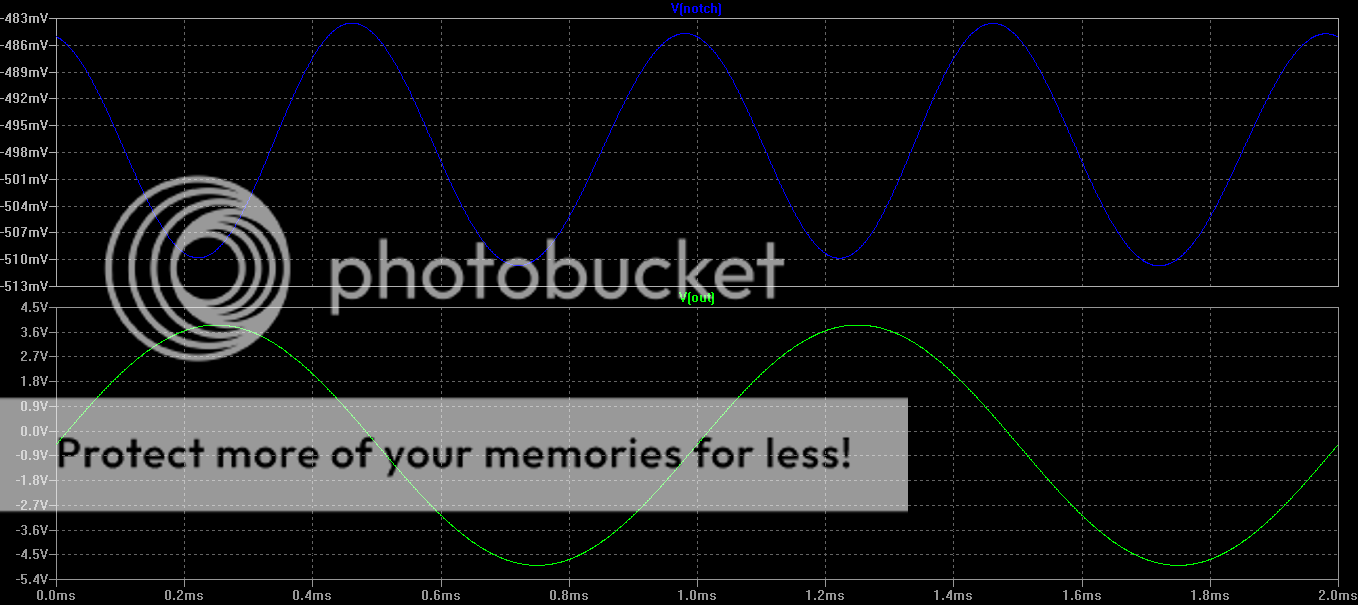
as shown from First Watt F7 review thread.
Another I found closely related is an observation by Eduardo de Lima from page 9 of Whysingle-endedtubeamplifiers.pdf :
In this case the speaker alone has around 2% of distortion between 100 Hz and 1000 Hz with 2.83 Vrms in the input (that corresponds to 1W in an 8 ohm load). We can see this in figure 1. In figure 2 we connect it to a SE amplifier with an average 0.8% 2nd harmonic distortion at this output level. It is easy to see the distortion addition between 150 Hz and 300 Hz and subtraction around 900Hz. We could say that, as an average, the distortion has increased. Figure 3 shows the same set up with the other polarity. We can see that the whole 150 Hz till 300 Hz region has reduced distortion and that around 900 Hz we have an increase in it. The overall effect seems to be a reasonable decrease in distortion.
Hi Indra,
Thank you for looking those discussions out! I do expect there to be a phase-measurement component, since phase has the most obvious effect on the sense of space-perception.
I will enjoy chasing some of those articles and tools down. The effect I observe is not exactly a front-to-back image corruption; but I suspect the same kind of approach to measurement will be needed; not just reading off the THD.
My impression is that for amplifiers, loss of spatial definition happens on all 3D axis, not constrained to a particular axis. However, I can not share much for non extensive experience and measuring gadgets available to me. THD is a lump sum, rather useful when measured by a microphone at listening position, quite uninformative for spatial impression correlation when measured as the output voltage of an amplifier. A harmonic spectrum distribution usually tell a bit more.... I suspect the same kind of approach to measurement will be needed; not just reading off the THD.
I've just made a dedicated PSU for the 01A, with matching veneer, rather than use the #26 PSU with a dropper resistor, as I had previously.
However, I had a senior moment, and wired the umbilical socket like the plug, so a mirror image! I only realised what I had done when I made a continuity check. But I only did that AFTER connecting it up and getting wrong voltages at the dummy load on the valve bases. It seems I fed the Coleman regs with the + and - reversed, which they took exception to. So I am getting 3.8V instead of 8.4V at the reg outputs, and 0.5V across the 2R2 filament load.
Time to contact Rod methinks, and find out what it will cost me to fix it! The HT is fine, 115V at the anode, and the raw filament voltage is the same as the other PSU, with 17V into the regs.
Never mind being too old to drive, (Prince Philip crash: Duke told witnesses 'I'm such a fool') I'm too old to solder!
Last edited:
- Home
- Amplifiers
- Tubes / Valves
- 01A question