I would suggest regular schottky junction diode such as the 1N5822 rather than a regular pn junction device for lower noise but more devices are required due to lower forward voltage drop.... Any other suggestions? ...
Last edited:
- the forward voltage will be more stable, and the signal resistance will be lower, if the current is increased to at least 250-500mA. The easy way to achieve this would be to filament-bias the diode string. 250mA would bring the signal resistance of the C3D02060A down to around 1Ω.
Filament bias would also increase the forward voltage, so you would need fewer diodes to get the same bias-voltage.
Hi Rod,
That was exactly my thought initially, but I decided to test it and listen to the stage which was revealing. I went back to my SiC tracing and zoomed the low current section. Between 5-6mA area where I'm currently operating at, seems to be quite linear:
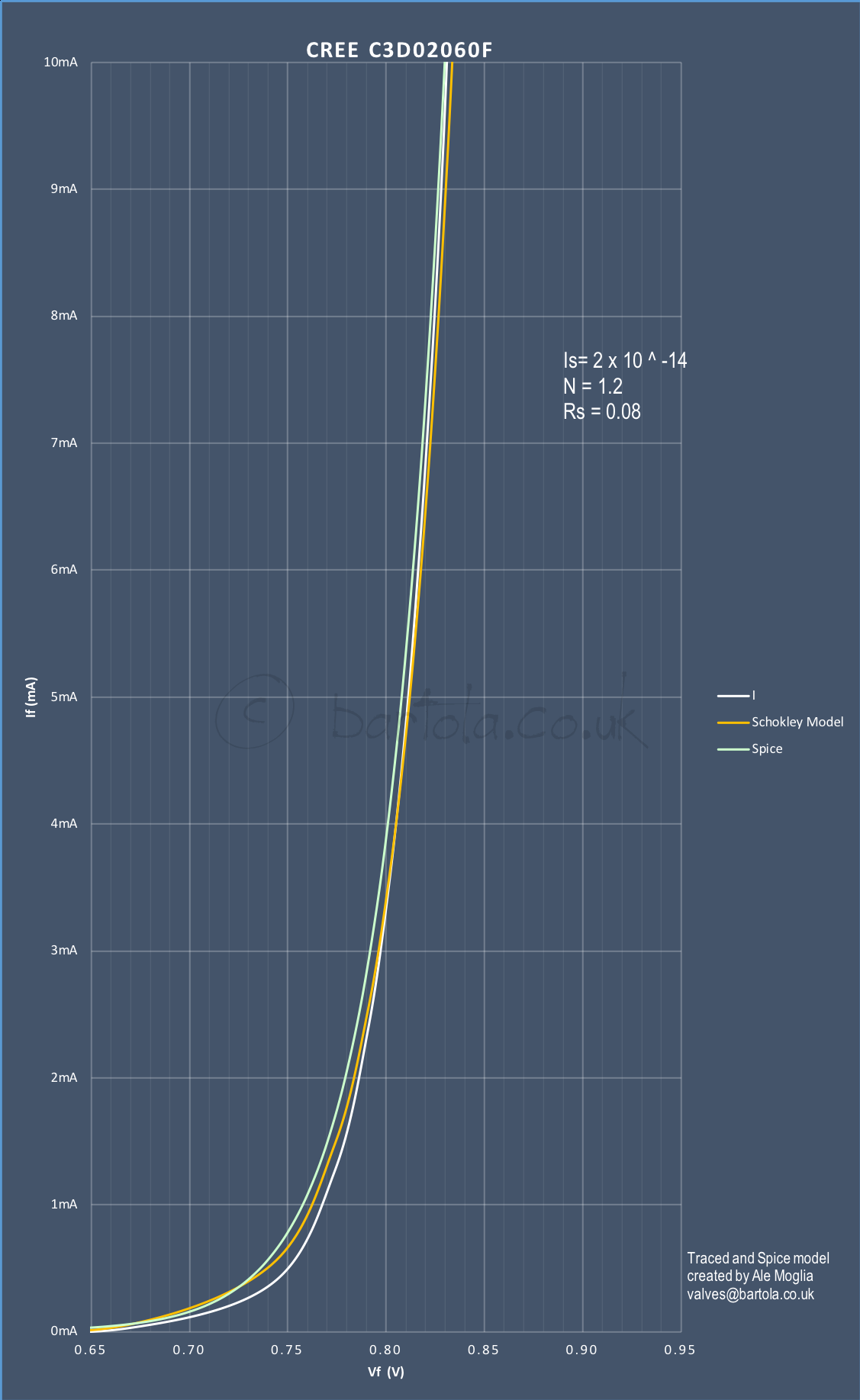
However, I agree fully that in filament bias will may be even better due to the current level will push down the dynamic resistance below 1ohm for sure.
Cheers
Ale
Not a problem and good to see you around here. Is a personal decision. I prefer the gyrator load, however chokes (if properly selected) are very good as well. On the flip side if you are looking at low current and high Ra DHTs, the choke isn't the best option and gyrator will work better overall. It sounds best in my opinion on those specific DHTs .Hey Ale, love your site, some really nice things on there that I want to try outRod's here too, have a bunch of his filament/bias boards here ready to go into amps.
Still on the fence about CCS/Gyrators in the anode circuit, have always preffered inductive loads and no solid state in the signal path. Maybe you'll convince me one day
sorry for the threadjack
Ale
Looks good, Ale - and filament bias looks the way ahead. I am sure we will be hearing from those that try it with filament bias soon.
As for other didoes to try, yes the 1N5822 is certainly worth a look. It is low-cost, and given the quantity of diodes Andy was discussing, it is worth a try.
Normal PN diodes are not noisy - in forward conduction mode, which is 100% of the time, in this circuit. Any sample should measure <1µV rms over the audio band, with 250mA flowing. They are worth investigating - even the standard-recovery parts - to reduce the number of parts.
Example: the ultra-cheap 1N4001 gives 0.8V forward voltage at 250mA (the 01A filament current) and <0.5Ω at that current, looking at the Fairchild curves. Much smaller than the others, too.
Forward voltage drop will also increase with more current, the number of diodes may need to be reduced (lower dynamic resistance bonus) to maintain bias.... However, I agree fully that in filament bias will may be even better due to the current level will push down the dynamic resistance below 1ohm for sure. ...
There is also an option to use a choke as Rmu on the gyrator.... On the flip side if you are looking at low current and high Ra DHTs, the choke isn't the best option and gyrator will work better overall....
We had a 9 preamp shootout today with Ale Moglia and Tony Rees, with one very significant result which I, for one, didn't expect. This was an 01A preamp (gyrator + source follower) that Ale had put together the day before on a hunch with 6 Cree C3D02060F diodes in the cathode. It was not only better than the other 10Y, 01A, EML20A, 6E6P-DR and 2P29L preamps (most in filament bias), it was comprehensively better in all ways. More transparent, better instrumental timbre, cleaner and all round more engaging and a better listen. If this can be reproduced for a variety of DHTs it marks a compete change in my builds from filament bias to SIC bias. I can't wait to get the soldering iron out - I want this sound in my system!
I'm sure Ale will be writing this up in more detail in his blog and with photos, so this is just advanced notice of what's coming!
'm glad you posted this, the 10Y was going to be one of my tube variants to try.
I think I'll stick with the 01A
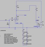
Here's a snapshot of current/voltage using Ale's model on 6 diodes
Attachments
Last edited:
'm glad you posted this, the 10Y was going to be one of my tube variants to try. I think I'll stick with the 01A
We only heard SIC diode bias in the 01A. Doesn't mean that there won't be equivalent benefits for all the other DHTs. I'm rebuilding a 2P29L preamp at the moment to see what that gives.
I have a string of 6 x CSD01060A on my 01A and the bias is exactly 5v. That's 0.83v each.
So, according the CSD01060A data sheet, I interpret that you run these diodes below 50mA, right?
All the best,
Ulrich
Should be around 4mA for an 01A.
Regarding plate chokes - yes, I like the NP Acoustics 136H 15mA amorphous plate choke. It's the best plate choke I've used. Nothing fancy cosmetically, just sounds good.
There is something that my ignorant person doesn't understand:
1-Filament of 01A current 250mA voltage 5V
2-If used filament bias resistor as per Moglia schematic 4V across 20 ohms = 200mA (starved) that's OK
3-If substitute the filament bias resistor for diode bias we can get the voltage needed but how can reach the 200mA of current for filament current?
4-Or the 200mA are supplied by Rod Coleman reg. and the string of diodes it's only to reach the voltage grid bias + current plate?
TIA
Felipe
For a 26 preamp you set up the Rod Coleman regs normally, not in filament bias. This may mean changing one of the resistors (was R8 on my older versions of Rod's regs). So you need the usual filament current and voltage from the reg - 1.5v at 1A or a bit less if you're starving it. You then set up the string of diodes to give you the required bias voltage across it, e.g. 10v.
We're also talking about using the diodes in filament bias, which is another way of doing it and may require heatsinks. But that's another story at the moment.
We're also talking about using the diodes in filament bias, which is another way of doing it and may require heatsinks. But that's another story at the moment.
Andy I supposed it's only to change the filament resistor for the diodes string?
As I said, if your 26 is in filament bias right now you need to change the supply voltage and one of the resistors in Rod's regs. If your 26 is on normal bias then as you say, you just change the resistor for the diode string.
 any ideas why the diodes are improving listening pleasure?
Thanks for experimenting....
Experimenting is the word! I've been trying for hours to get my 2P29L version with SIC bias to work. Since these are plastic bodied devices, I started off with the "good idea" of putting a long M3 screw through the holes in the 12 diodes and keeping them apart with M4 nuts. Please explain this to me - can these devices inductively couple or what? Anyway, voltages were all over the place.
I then took a length of 28 way solder tag strip and soldered the 12 diodes onto that. This immediately gave me the 10v bias I was after.
WTF.... Ideas?
Last edited:
Last edited:
I was connecting the diodes correctly when they were all held together by the long M3 screw. I can only guess that there was something inductive going on.
Anyway, all is working now and I have my 2P29L back sounding nice. The SIC diode bias gives a little more clarity. I think it's a worthwhile mod.
Anyway, all is working now and I have my 2P29L back sounding nice. The SIC diode bias gives a little more clarity. I think it's a worthwhile mod.
Not sure that would work in filament bias?For a 26 preamp you set up the Rod Coleman regs normally, not in filament bias. This may mean changing one of the resistors (was R8 on my older versions of Rod's regs). So you need the usual filament current and voltage from the reg - 1.5v at 1A or a bit less if you're starving it. You then set up the string of diodes to give you the required bias voltage across it, e.g. 10v.
We're also talking about using the diodes in filament bias, which is another way of doing it and may require heatsinks. But that's another story at the moment.
I was connecting the diodes correctly when they were all held together by the long M3 screw. I can only guess that there was something inductive going on.
If the case is a dead short to pin 1, a plastic screw should work well.
These TO220 devices have a plastic case so no dead shorts. I also used some CSD01060A which does have a metal case, and for that I used short nylon spacers which worked fine. Something about this long M3 screw going through all the devices. I just realised I didn't ground the screw - it was floating. Maybe that would fix it. But something "screwy" going on here. When the devices are mounted on tag strips they work fine.
Interesting. I wonder what range of voltage fluctuations you got with spaced stacking on the M3 screw? Good the issue is fixed now. I imagine ideally you would have wanted all the diodes to be the same temperature and running cool for best voltage stability. So you probably wouldnt have kept them stacked anyway as the inner diodes would theoretical have warmed up more with infrared radiation from the adjacent devices. Practically do the diodes warm up at all with such tiny loads?
More importantly with the SICs on both the 01A and 2P29L, which valve do you like more? Does the venerable thoriated 01A still have the magic. Thanks again.
More importantly with the SICs on both the 01A and 2P29L, which valve do you like more? Does the venerable thoriated 01A still have the magic. Thanks again.
- Home
- Amplifiers
- Tubes / Valves
- 01A question