

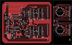
Next week i will design a 1 layer PCB for it. And test it.
About the schematic.
The input potmeter generates a voltage between 0 and 999mv on the input of IC C520D(CA3162). This IC converts voltage to 7 segment display. Because the nixie tubes can not multiplex as fast as a led display there is a buffer(IC 74LS75) after IC C520D. Next there is IC74141 who decodes bcd 7 segment to decimal and drives the IN-4 nixie. The powersupply generates three voltages, +5v for the logic, +12v for the sensor and +170v for the nixie tubes. For the 170v supply i used a small step up converter from ebay. It is designed for nixie tubes and convert 12v to 170v.
Below a photo from the dutch builder.
Attachments
Last edited:
Hi gideon1990,
Koifarm did this the exact correct way. I would have used the CA3162 and the high voltage driver. Your ICL7107 would have lasted until you turned the power on - poof! To use your choice of IC, you would have needed to put a high voltage buffer chip between it and the display. Since this project only needs 3 digits and doesn't go negative (-99 is the max for CA3162), the choice of chip was perfect!
Hi Koifarm,
That's a really nice project. Great thinking of delaying the scan rate on the Nixie driver. I've seen enough ghosting with nixies to last a lifetime. The Dutch built project looks fantastic! How close will yours come to that type of design?
-Chris
Hi Koifarm,
That's a really nice project. Great thinking of delaying the scan rate on the Nixie driver. I've seen enough ghosting with nixies to last a lifetime. The Dutch built project looks fantastic! How close will yours come to that type of design?
-Chris
Hello Chris,
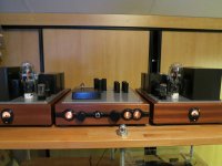
i will use it with a passive volumecontrol with source selector. In a high gloss black housing. An extra nixie i shall use as source indicator. The design looks like my record player.
Attachments
Hi Ronny,
You did a splendid job on that table sir!
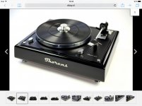
I am using an old VMS-30E MKII on the TD-125 MKII and a 540 on the other. The VMS-30E MKII doesn't do enough wrong to warrant replacement. There is an older VMS-20E MKII sitting in the wings in case of failure. It is less nice than the 30E, but still not unpleasant.
For the TD-125 MKII I am rethinking the suspension. It's too live in this house to enjoy, so instead of springs, there is another type of spring with very high internal damping that I'm going to try. The new type of spring is made from twisted steel and formed into loops. That allows them to deform easily, and yet absorb the energy so that there isn't any bounce when they return. I don't know if the concept will work, but think it's worth a try. Any thoughts?
I'll have to have a search on Ebay when the time comes to rebuild these tables. Thank you for letting me know.
-Chris
You did a splendid job on that table sir!
I am using an old VMS-30E MKII on the TD-125 MKII and a 540 on the other. The VMS-30E MKII doesn't do enough wrong to warrant replacement. There is an older VMS-20E MKII sitting in the wings in case of failure. It is less nice than the 30E, but still not unpleasant.
For the TD-125 MKII I am rethinking the suspension. It's too live in this house to enjoy, so instead of springs, there is another type of spring with very high internal damping that I'm going to try. The new type of spring is made from twisted steel and formed into loops. That allows them to deform easily, and yet absorb the energy so that there isn't any bounce when they return. I don't know if the concept will work, but think it's worth a try. Any thoughts?
I'll have to have a search on Ebay when the time comes to rebuild these tables. Thank you for letting me know.
-Chris
Chris,
i have no experience with other springs. My turntable is mounted on a stone wall.
The link to the nice upgrade parts: http://stores.ebay.nl/art-and-sound?_trksid=p2047675.l2563
And now try to stay on topic. I know it is difficult because there are a lot of nice things to DIY in audioland.
Ronny
i have no experience with other springs. My turntable is mounted on a stone wall.
The link to the nice upgrade parts: http://stores.ebay.nl/art-and-sound?_trksid=p2047675.l2563
And now try to stay on topic. I know it is difficult because there are a lot of nice things to DIY in audioland.
Ronny
Believe it or not, a well-sealed 2 kg bag of cornstarch, sewn into a pretty pillow cover (i.e. cornstarch in triple zip-lock bags of the 1 gallon size, then put in a Jacquard type heavy throw-pillow cover), does dampening like a charm. Remarkably so. I've been doing it for years, and since its cheap and easy, so have my friends. It works.
GoatGuy
GoatGuy
- Home
- Amplifiers
- Tubes / Valves
- Retro nixie volume indicator