I just fired up an old Magnavox tube stereo console (late 50's, early 60's?) and everything was fine at first. Then, I noticed the right speaker wasn't working, it was barely audible with distortion. When I power the unit off, the right channel is suddenly became clear and strong for an instant just before shutdown. If I let it sit for awhile before powering on the console, the right channel works for about 30 seconds and the same results that I described above occur.
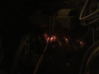
So, I pulled off the rear panel and noticed that one tube was glowing brighter than the others on the power amp. There's a section with four tubes in a row (6BQ5) and the third one was glowing hotter. So, I powered it down for a while and swapped the third tube for the second. When I powered it back on, the same thing occurred, the different tube in the third slot was glowing brighter and the audio cut out again. I know that it's a bad idea, but I lightly touched the tubes and that third tube is super hot compared to the others.
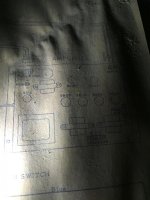
I'm posting the schematic that was inside the rear cover and another photo to demonstrate just how much brighter that one tube is than the others.
What do I do now? Any help would be appreciated.
So, I pulled off the rear panel and noticed that one tube was glowing brighter than the others on the power amp. There's a section with four tubes in a row (6BQ5) and the third one was glowing hotter. So, I powered it down for a while and swapped the third tube for the second. When I powered it back on, the same thing occurred, the different tube in the third slot was glowing brighter and the audio cut out again. I know that it's a bad idea, but I lightly touched the tubes and that third tube is super hot compared to the others.
I'm posting the schematic that was inside the rear cover and another photo to demonstrate just how much brighter that one tube is than the others.
What do I do now? Any help would be appreciated.
Attachments
Last edited:
looks like bias voltage troubles! what you do now depends on your skill and knowledge of tube circuits. from the fact that you called the tube layout chart a schematic i take it that your not well acquainted with tube circuits?
don't keep running the amp with this problem it can kill the tubes.
see if you can find a model number for your console.
don't keep running the amp with this problem it can kill the tubes.
see if you can find a model number for your console.
Last edited:
The tube in the fourth slot might be weak, so that the third slot gets to do all the work. It is a push-pull amplifier, meaning two tubes per channel (slot 1-2 and slot 3-4). They are supposed to do half the work each, but if one doesn't work right, the other gets to all the work by itself. This overloads the tube.
You need to replace the the two tubes in slot 3-4 with a matched pair.
To super clarify, put tube 1-2 in the 3-4 positions, and vice versa. If one of the tubes in position 1-2 now glows red, you know for sure you have a bad tube.
You need to replace the the two tubes in slot 3-4 with a matched pair.
To super clarify, put tube 1-2 in the 3-4 positions, and vice versa. If one of the tubes in position 1-2 now glows red, you know for sure you have a bad tube.
well if he wants to potentially kill an expensive set of "matched tubes" he can try that. to my knowledge loss of conduction in a push pull pair is not going to force the other half into working harder. "red plating" as shown in the picture is a pretty clear indicator of missing bias voltage.
Last edited:
well if he wants to potentially kill an expensive set of "matched tubes" he can try that. to my knowledge loss of conduction in a push pull pair is not going to force the other half into working harder. "red plating" as shown in the picture is a pretty clear indicator of missing bias voltage.
Think about a PP pair with common cathode bias resistor. One tube has loss of conduction. Then the bias simplified is only half and the healthy tube is going red. I had it once, since that case I implement always with separate cathode resistors and caps.
Hans- Georg
PS: This is just a general comment, would be good to see the schematic.
Last edited:
The tube in the fourth slot might be weak, so that the third slot gets to do all the work. It is a push-pull amplifier, meaning two tubes per channel (slot 1-2 and slot 3-4). They are supposed to do half the work each, but if one doesn't work right, the other gets to all the work by itself. This overloads the tube.
You need to replace the the two tubes in slot 3-4 with a matched pair.
To super clarify, put tube 1-2 in the 3-4 positions, and vice versa. If one of the tubes in position 1-2 now glows red, you know for sure you have a bad tube.
This is assuming that it is cathode biased and each channel has one cathode resistor for both EL84 valves. Without a schematic and measurements you're only guessing.
If I were to guess, my first bet would be a leaky coupling cap, next a bad solder joint, shorted bypass cap on the cathode resistor of valve number 3 or a loose socket pin.
Get it to somebody who knows valve amps.
Don't go poking inside unless you know what you're doing. High voltages can bite badly.
Loss of bias for that socket, yes, but my money is on a leaky coupling cap to the grid of that tube. That allows positive DC on the grid causing any tube in that socket to conduct way too hard. Pull those tubes and measuer the voltage on the grid pin of each socket, see if that socket comes up way different.
With all respect, I would not go changing tubes around experimentally when one red-plates. That is a destructive move and could/will ruin the beleagured tube in not many seconds. (The red-plating one would in all likelyhood be destroyed by now.) As said there could be several reasons, but the only way to remedy would be to investigate/measure with a multimeter - not try out with a different tube every time!
The problem should be easy to find; failure of a cathode bypass capacitor, leaking coupling capacitor - anything removing bias from the cathode-g1 circuit.
The problem should be easy to find; failure of a cathode bypass capacitor, leaking coupling capacitor - anything removing bias from the cathode-g1 circuit.

if the schematic that tesla88 posted is the circuit used in the amp that the OP has,with a common cathode resistor for all the output tubes, why is only 1 tube "red plating" hard? we are supposing one tube is bad (loss of conduction) would the change not affect the other three rather than just one?
Enzo's premise of a bad/leaky coupling cap i think is the most likely scenario here i think.
without the OP getting back to us with details all we can do is wait.
Enzo's premise of a bad/leaky coupling cap i think is the most likely scenario here i think.
without the OP getting back to us with details all we can do is wait.
Last edited:
Thanks for the replies everyone. Sorry it's taken so long to get back to this thread but I had a weekend away. Please be patient with me on this one as I'm not experienced with this sort of thing. I know the general terms, own soldering equipment and a digital multi-meter but my experience is with passive guitar electronics. I've only ever used the multi-meter to test guitar pickups and test for continuity.
I do realize that what I posted wasn't a schematic. Bad choice of terms.
Right now, I'm not at home so I can't tell what model of power amp I have. I did snap a photo of the model number from the console which is 1MV359R. If I can find time tonight, I'll work on disconnecting the amp and getting it out of the console. I'll post back the amp model number as soon as I find it.
- Status
- This old topic is closed. If you want to reopen this topic, contact a moderator using the "Report Post" button.
- Home
- Amplifiers
- Tubes / Valves
- One tube brighter/hotter than the others