At first thank you very much for your patience. I used a signal generator and found that with about 475mv I have 5w rms in charge (8ohms). If the signal increases at the input the distortion starts to increase significantly. I can not get the distortion value at 5W but on the oscilloscope the sinusoidal wave at this point is perfect, it distorts if it starts to increase.... The schematic is that of the artosalo (post # 7) with the difference in cathode resistance that is 390 ohms. The transformers are the TTG-EL34SE (toroidy) with UL tap at 43%. I was hoping to get more power output as the project announces 10W + 10WEL34, and I have read on many websites that the power for EL34 SE could reach those values. Thanks a lot for the help
josino,
Your EL34 has 72 mA quiescent current. If the signal to the EL34 grid was strong enough to cause the EL34 current to rise to 2x that current (142mA), and then down to 0mA, that change would be 72mA (+ / - 72mA).
If you drive the EL34 to 0 mA current, the signal will be clipped, and very distorted. The tube curves are quite distorted when the current is low, i.e. 10mA or 15mA.
72mA (+ /- 72mA) into 3200 Ohms
Power = ((Peak Current Squared) * Impedance)/2
((0.072A Squared) * 3,200 Ohms)/2
(0.005184 * 3200)/2 = 8.2944 Watts rms (but very distorted).
72mA (+ /- 55.9mA) into 3200 Ohms
((0.0559A Squared) * 3200 Ohms)/2
(0.003125) * 3200)/2 = 5 Watts rms
I believe you are doing good with 5 Watts relatively undistorted.
The schematic is that of the artosalo (post # 7) with the difference in cathode resistance that is 390 ohms....
I made a simulation with 390 ohms at the cathode and 355 V as +Ub.
Anode current was 60 mA and anode dissipation 20 W. So it could be 5 W higher.
Max. output power should be some 8...8.5 W when UL-connected.
How much was the actual anode current in your case, with 390 ohms at the cathode ?
I was hoping to get more power output as the project announces 10W + 10WEL34, and I have read on many websites that the power for EL34 SE could reach those values.
That is quite optimistic value and only possible in pentode mode.
Philips data sheet gives the following values for pentode connected EL34 SE:
Ua = 265 V, Ia = 100 mA, Rl = 2.0k, Pout = 11 W, THD = 10%.
Attachments
artosalo,
Josino's amplifier has 72mA and a 3.2k Ohm output transformer.
That combination is only going to give about 5 Watts at low distortion.
Yes, if you change the circuit parameters to pentode mode, 100mA and 2.0k Ohm OPT primary, you do get more power (and 10% distortion which is quite high).
265V and 100mA gives 26.5Watts plate dissipation, which is more than the EL34's 25Watt plate dissipation rating.
At that operating condition, the pentode plate resistance is about 15k Ohms.
Pentode mode in that configuration that does not have negative feedback,
gives a damping factor of far less than unity. 2k/15k = Damping Factor of 0.133
At least Ultra Linear mode with a 2k Ohm OPT, and without global negative feedback will have a damping factor closer to 0.5 or 1.0. The 3.2k OPT will have a better damping factor than the 2.0k OPT.
If you use 10 dB of negative feedback, the amp gain will only be 0.316 of what it is with no negative feedback.
If you use 20 dB of negative feedback, the amp gain will only be 0.1 of what it is with no negative feedback.
Triode mode, no global negative feedback, and 3.2k Ohm OPT; will give about 1/2 the power of ultra linear mode, about 1/2 the gain of ultra linear mode, but will give a damping factor of about 2 to 3, at low distortion.
Power, distortion, gain, and damping factor: a simple EL34 SE circuit can not give all 4 of those at the same time.
Last edited:
Great explanation, thank you very much. In the next few days I will replace the diode grinding for 5AR4. The voltage B + goes down a little, the power dissipated in the EL34 also ... I use this mountain to listen to music in a room with about 15m2, 5Wrms is more than enough for this place. Then I will communicate the results ..... Thank you very much.
Hi all
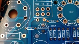
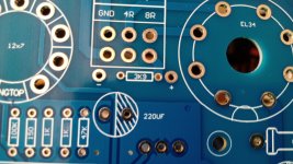
I´m trying to build this Aliexpress amp kit. Checking the pcb I found two (+) and (-) points, possibly to measure voltage across 3K9 resistor. As far as I could learn this are the NFB resistors at 8ohm OPT tap. Please inform, what are the pourpose of this measuring voltage? Thanks in advance for comments and assistance
I´m trying to build this Aliexpress amp kit. Checking the pcb I found two (+) and (-) points, possibly to measure voltage across 3K9 resistor. As far as I could learn this are the NFB resistors at 8ohm OPT tap. Please inform, what are the pourpose of this measuring voltage? Thanks in advance for comments and assistance
Attachments
Last edited:
Do you have a schematic for this amp?I´m trying to build this Aliexpress amp kit.
jeff
Caveat Emptor, buyer beware.
Sorry.
Hoping that a thread from 2015 that is not solved in 2023, requires some extra work on your part.
The PCB you have may, or may not, even be the original one.
Drawing out the complete PCB is a pain.
But it can help both now, and in the future if anything goes wrong.
Sorry.
Hoping that a thread from 2015 that is not solved in 2023, requires some extra work on your part.
The PCB you have may, or may not, even be the original one.
Drawing out the complete PCB is a pain.
But it can help both now, and in the future if anything goes wrong.
- Home
- Amplifiers
- Tubes / Valves
- 10W+10W EL34+ECC83 single-ended Class A Stereo amplifier Kit wlx