Hi ok but if I don’t want to modify the circuit and just Try the 12AU7 with adapters, is it ok?
I can put tubes in an adapter lol
But I’m not too tech savvy so I’m not sure i would venture into adding the resistors.
But I can have a tech do it for me based on your post.
What does adding the resistors do?
Thx
I can put tubes in an adapter lol
But I’m not too tech savvy so I’m not sure i would venture into adding the resistors.
But I can have a tech do it for me based on your post.
What does adding the resistors do?
Thx
I don't understand what all the fuss is about.
Have a look at the full kit of parts in post#12 and you will be able to see that the adapter is nothing more than a plastic tube with tinned copper wires from the octal base to the 9 pin socket.
The only item not shown there is the two data sheets.
It is nothing more than a pin-out changer.
Have a look at the full kit of parts in post#12 and you will be able to see that the adapter is nothing more than a plastic tube with tinned copper wires from the octal base to the 9 pin socket.
The only item not shown there is the two data sheets.
It is nothing more than a pin-out changer.
Hi
I know that but my question is it safe to try it in my headphone amp since the 6SN7s are driving the power tubes. I ask this because one of the other posters had mentioned that I may not be safe in such a case.
As opposed to in a preamp where there are no power tubes.
Thx
I know that but my question is it safe to try it in my headphone amp since the 6SN7s are driving the power tubes. I ask this because one of the other posters had mentioned that I may not be safe in such a case.
As opposed to in a preamp where there are no power tubes.
Thx
maddmaxxdrummer,
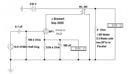
The schematic in your post (# 17) does not cause high dissipation of the dual triode input tube.
The 6SN7 can dissipate more than the 12AU7, but the input stage is at fairly low current, and dissipation in that circuit is low.
Yes, the 12AU7 is safe there (as long as the adapter pinout to pinout is correct).
In your case (if your amp actually is just like the schematic), using an adapter and a 12AU7 is "Plug and Play". You are set to go.
For some other uses and circuits of the 6SN7 where the tube is used at its maximum dissipation ratings, putting a 12AU7 there would be "Plug and Pray". Hot, Hot, Hot.
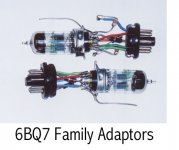
Adapters
The adapters I built were used to sub tubes of the 6BQ7 family into 6SL7 & 6SN7 sockets. The cathode resisters in the 6SN7 sub are inserted to reduce the 6BQ7 gain which would be about double that of the 6SN7 it was replacing.
Your adapters need only to be connected to the proper pins at each end. But adding 1/2 watt CC resisters in the grid leads would be good insurance to avoid parasitic oscillations. The 12AU7 should have no problem at all in this circuit.
The circuit as shewn in #17 will not achieve 6.8W per channel. But still more than enough for headphones.")
The adapters I built were used to sub tubes of the 6BQ7 family into 6SL7 & 6SN7 sockets. The cathode resisters in the 6SN7 sub are inserted to reduce the 6BQ7 gain which would be about double that of the 6SN7 it was replacing.
Your adapters need only to be connected to the proper pins at each end. But adding 1/2 watt CC resisters in the grid leads would be good insurance to avoid parasitic oscillations. The 12AU7 should have no problem at all in this circuit.
The circuit as shewn in #17 will not achieve 6.8W per channel. But still more than enough for headphones.
Hi
I know that but my question is it safe to try it in my headphone amp since the 6SN7s are driving the power tubes. I ask this because one of the other posters had mentioned that I may not be safe in such a case.
As opposed to in a preamp where there are no power tubes.
Thx
The main difference is that the 6SN7GTA/B were designed for use as TV vertical deflection oscillators/amps. For this, the original design saw an increase in PD, grids hardened to allow for vgk > 0V, and also increased voltage handling. You wouldn't use the 12AU7 for this, due to the lower voltage handling. This isn't going to be a big problem for the vast majority of audio usage as voltages don't usually run anywhere near the voltages caused by flyback in vertical deflection systems.
Thus Spake the Oracle. Its just a proof that your headphone amp will not deliver 6.4 watts per channel. The amp total both channels might deliver 6.4 watts, on a good day. Running downhill!!
When are we going to see your adapter? You've been talking about it for six weeks now. Any good experimenter would be done five weeks ago & moved on to the next big thing.
When are we going to see your adapter? You've been talking about it for six weeks now. Any good experimenter would be done five weeks ago & moved on to the next big thing.
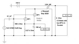
Here is the simulation with the OPT primary set to 2.5K. That requires two of the 6P1s in parallel. The bottom line is still the same, ~3.3 watts per channel.
If you could measure the primary & secondary resistance of the OPT that data could be stuffed into the simulation. And a result closer to reality possible.
Many home grown amps & quite few of those professionally built do not meet the claimed performance on the test bench. But no matter, if the user is happy with the performance that is what matters,
Attachments
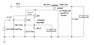
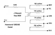
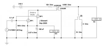
6P1 Amp with Hammond 125DSE
This simulation shews the audio available after the winding copper losses. Other losses in the OPT are not shewn, that would be in the iron, eddy currents & hysteresis. And more in the copper if one adds in skin & proximity effects. The copper wire in the winding has higher resistance at AC than at DC, depends on frequency. And higher resistance closer to the center of the winding cross section.
You get the idea, it ain't simple & wastes some of your hard won audio.
Attachments
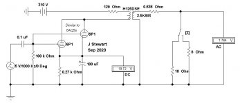
Damping Factor Calcs for 6P1 x2 Amp Without OPT Losses
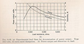
Stuffing the numbers in the simulations into the HP67 I got internal impedance of the amp without the OPT losses to be 3.636 ohms on the 8R tap. So DF is 2.2, typical for a triode connected to a steep loadline. The designer has chosen to go with a steep loadline (2.5K) in order to maximize power output at the expense of DF. The steep loadline is also such that distortion will be higher than what something like a 3-3.5K loadline would yield.
The power output & distortion curve for the 2A3 is typical of all Class A triodes, only the scale factors are different.
Attachments
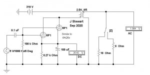
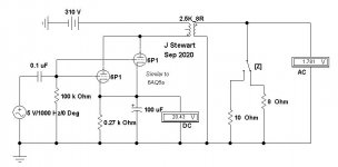
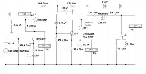
DF Calcs for 6P1 x2 Amp With OPT Losses
Stuffing the numbers in the simulations into the HP67 I got internal impedance of the amp with the OPT losses to be 4.786 ohms on the 8R tap. So DF is 1.67. Looks like the OPT has added 1.15R to the audio path.
Stuffing the numbers in the simulations into the HP67 I got internal impedance of the amp with the OPT losses to be 4.786 ohms on the 8R tap. So DF is 1.67. Looks like the OPT has added 1.15R to the audio path.
Attachments
Nice info but I’m not at that level...
I tried swapping OPT with same specs. 2.5k:4,8ohm.
But better iron..... but the sound is all crackling and distorted...
doesn’t work. The new ones are 12(H)
I don’t know the inductance of the original... maybe it’s different so maybe that’s why it doesn’t work.. maybe some changes in some components are needed for this to work.
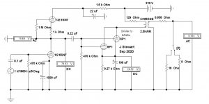
Slightly Modified 6P1 x2 Amp Circuit
Audio amps are usually designed to deliver full output at about One Volt in. The circuit as is goes all the way with only a 0.25 volt signal. Here is a simple mod using all the same tubes so that about One volt will fully drive the amp. Both before & after circuits are shewn.
The 6P1 looks a lot like a ruggedized 6AQ5, the plate curves in both triode & pentode are very similar. The 6P1 heater needs a little more current, probably the cathode build is more robust & needs extra current to reach operating temperature. My thoughts, anyway.
Attachments
- Home
- Amplifiers
- Tubes / Valves
- Has anyone tried a "12AU7 to 6SN7 Adapter"?