I'm having the weirdest problem with a little balanced-out preamp I'm building. I'm not getting heater voltage to the signal tubes, but I don't understand why.
I'm using an AC heater supply.
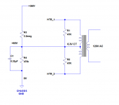
I need to float the AC heaters +60V above ground. I've done this with a voltage divider between B+ (360V) and ground, as shown in the attached schematic. (2.2M and 470k resistors from B+ to ground, with a 0.33uF cap in parallel with the 470k resistor.)
The transformer I'm using has a 6.3V CT winding. I have 47R resistors forming a center tap, in parallel with the transformer center tap for the heaters.
Looking at the schematic, should I not connect the 6.3V winding's center tap, and just use the 47R resistors to create the center tap?
I have both the 47R resistors and the 6.3V winding's center tap connected to the same place (+60V point on the voltage divider). Maybe that's why the signal tubes' heaters aren't lighting up. Why would this be?
I'm using an AC heater supply.
I need to float the AC heaters +60V above ground. I've done this with a voltage divider between B+ (360V) and ground, as shown in the attached schematic. (2.2M and 470k resistors from B+ to ground, with a 0.33uF cap in parallel with the 470k resistor.)
The transformer I'm using has a 6.3V CT winding. I have 47R resistors forming a center tap, in parallel with the transformer center tap for the heaters.
Looking at the schematic, should I not connect the 6.3V winding's center tap, and just use the 47R resistors to create the center tap?
I have both the 47R resistors and the 6.3V winding's center tap connected to the same place (+60V point on the voltage divider). Maybe that's why the signal tubes' heaters aren't lighting up. Why would this be?
Attachments
I have both the 47R resistors and the 6.3V winding's center tap connected to the same place (+60V point on the voltage divider). Maybe that's why the signal tubes' heaters aren't lighting up.
You don't need the two 47 ohm resistors since you have a center tap. They are used if there is no CT available.
There may be a bad connection in your filament circuit if the heaters don't light.
Try without the HV on and see where you can measure 6VAC.
Simplification is good, in this case. I took away the 47R resistors and the problem cleared up. I still don't know what the problem was, but it's OK now. Thanks. I'm not sure why I was thinking the 47R resistors were a good idea.
What about film caps to bypass the heaters to ground at the tube sockets? This is described in Morgan Jones' Valve Amplifiers, and is supposed to shunt RF or switching transients on the heater supply to chassis. I have a .022uF cap going from pin 4 to chassis and another from pin 5 to chassis, at the tube sockets (9-pin mini). Is that a good idea?
--
What about film caps to bypass the heaters to ground at the tube sockets? This is described in Morgan Jones' Valve Amplifiers, and is supposed to shunt RF or switching transients on the heater supply to chassis. I have a .022uF cap going from pin 4 to chassis and another from pin 5 to chassis, at the tube sockets (9-pin mini).
This is seldom done, even in tube tuners, but make sure that the cap voltage ratings are adequate,
because of the DC level shift present.
This is seldom done, even in tube tuners, but make sure that the cap voltage ratings are adequate,
because of the DC level shift present.
630VDC should be adequate, no? That's what I had on hand, so that's what's in there.
I'm getting a measured lift for the heaters of about +50V from ground, which is adequate. (I expected +67V from the 2.2M and 470k resistors I used, but I'm not getting that. Another mystery.) Would 100VDC rated caps be sufficient in this case?
--
I'm getting a measured lift for the heaters of about +50V from ground, which is adequate.
(I expected +67V from the 2.2M and 470k resistors I used, but I'm not getting that.
Another mystery.) Would 100VDC rated caps be sufficient in this case?
Try scaling down the resistors, keeping the same ratio. Say, 220k and 47k instead.
Any cap rated at 100VDC should be ok. Maybe the cap leakage is shunting the lower resistor.
Might be better to call this 'biasing the heaters' - 'floating' means no connection to anything else, which heaters should never be.rongon said:I need to float the AC heaters +60V above ground.
The 47R resistors you originally had in the circuit would do no harm, so you must have had a wiring error or a faulty component.
Small caps from heater to chassis are sometimes used in RF equipment to stop RF leaking from one stage to another. Not really necessary for audio.
Thanks rayma.
I'll try going in and getting that 67V I wanted for lifting the heaters, maybe later. The cathode of the second stage (a cathodyne/concertina) is sitting at +130V, so lifting the heaters by 50V puts the heater-to-cathode voltage at -80V, which is within spec for a 6DJ8.
The problem with scaling down the resistors means they need to be rated at 1W, or 2W for a margin of safety, which I don't have on hand in high values like that. I'll have to order some.
Everything is working now, so thanks again for your help with this.
I'm comparing this balanced-out line amp (very similar to SY's ImPasse) to an unbalanced out line amp feeding a pair of Edcor 1:1 transformers used as phase splitters at the inputs of my power amp. Going back and forth between them, seeing if I end up liking one better than the other. They both must be OK, because now that the transformers have broken in, the two line amps sound very similar to each other. There are subtle differences, but it's hard to say which I like better. All good fun.
--
Might be better to call this 'biasing the heaters' - 'floating' means no connection to anything else, which heaters should never be.
Thanks, you're absolutely right!
I'm happy to report that I'm getting no hum at all from the speakers. So I guess the heater wiring is good enough. You're right, I must have had some kind of dumb wiring error.
--
It is quite possible your measuring instrument is pulling down the heater elevation voltage when you measure it. If it has a 1M input impedance , this in parallel with the 470K will reduce the total impedance to 330K.
I also think your resistor values are much too high. Many tubes specifiy a maximum heater to cathode resistance of 47K or less. You could usefully reduce yours by a factor of 10. I would also advise significantly increasing the decoupling capacitor. I typically use 47uF.
CHeers
Ian
I also think your resistor values are much too high. Many tubes specifiy a maximum heater to cathode resistance of 47K or less. You could usefully reduce yours by a factor of 10. I would also advise significantly increasing the decoupling capacitor. I typically use 47uF.
CHeers
Ian
It is quite possible your measuring instrument is pulling down the heater elevation voltage when you measure it. If it has a 1M input impedance , this in parallel with the 470K will reduce the total impedance to 330K.
I also think your resistor values are much too high. Many tubes specifiy a maximum heater to cathode resistance of 47K or less. You could usefully reduce yours by a factor of 10. I would also advise significantly increasing the decoupling capacitor. I typically use 47uF.
CHeers
Ian
Thanks for that info Ian. That's new to me, so it looks like I'm learning something!
I was having problems with hissing noises using a 6X4 rectifier tube. That was cured by swapping in a pair of UF4007's, so I figured the 6X4 just couldn't handle the 36mA of current draw. That was a surprise, but I now see that I may have goofed.
I'll swap in 47k 1/2W and 220k 1W parts instead of the 470k and 2.2M I have in there now. If I get the 67V bias I expected, then your point will be proven.
--
The problem with scaling down the resistors means they need to be rated at 1W,
or 2W for a margin of safety, which I don't have on hand in high values like that.
Just use 4 of the same value in series/parallel to quadruple the power rating.
I was able to pull out a 47k 1W and a 220k 1W from my junkbox stash. Put them in, and....
53.7V bias on the heaters.
Strange. Maybe I'm doing the math wrong?
The B+ is 390V
I want to drop that across my voltage divider, and get 60V to 70V bias for the heater supply. I figured 330 + 60 = 390, so that's the ratio. 33:6 or approximately 5:1.
I took 47k and 220k. Not quite 5:1, but that's OK.
220k + 47k = 267k total resistance.
390V / 267k = 0.00146A (1.46mA) total current through the voltage divider.
47k * 0.00146 = 68.62V
220k * 0.00146 = 321.2V
68.62V + 321.2V = 389.82V (very close to 390V)
I'll bet I'm doing that all wrong. I sense a learning experience coming...
--
53.7V bias on the heaters.
Math seems ok, should be around 68V. Maybe your meter is loading the divider.
Last edited:
What do you think of electrostatically coupled common-mode noise via the heater windings, which may include mains-borne noise, rectification noise or EMI. As far as I remember this is what Morgan Jones was on about. He also recommended CM chokes.Small caps from heater to chassis are sometimes used in RF equipment to stop RF leaking from one stage to another. Not really necessary for audio.
Also, link to recent similar thread.
I once had a rectifier pulse on a DC biased AC heater line. No amount of decoupling would shift it. Eventually I just removed the bias and grounded the secondary CT. Pulse gone. I learnt from that not always to raise heater lines to remove noise; sometimes just grounding them is better.
What do you think of electrostatically coupled common-mode noise via the heater windings, which may include mains-borne noise, rectification noise or EMI. As far as I remember this is what Morgan Jones was on about. He also recommended CM chokes.
Also, link to recent similar thread.
MJ also talked about CM coupling through heater-to-cathode leakage. That was one of the reasons that he used a string of emitter followers for heater biasing rather than just resistors. Personally, I disagree with that approach- if a tube has significant heater-to-cathode leakage, replace the tube.
- Status
- This old topic is closed. If you want to reopen this topic, contact a moderator using the "Report Post" button.
- Home
- Amplifiers
- Tubes / Valves
- Help with floating AC heaters (please)