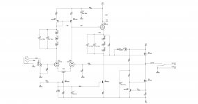
Here’s an idea for a direct-coupled tube (or tube-MOSFET) headphone amplifier. It is a simple variant on a widely used circuit, so I’m sure something similar is already out there. A DC level shifter allows the circuit to be direct coupled, with the output at 0 V DC, while also allowing the tubes to operate at high voltages (200 V), where they work best. I can’t claim any creativity on the level-shifter idea, since similar techniques were used to direct-couple tube operational amplifiers back in the 1950s & 1960s. Back then, neon lamps were used instead of the zener diodes. But I haven’t seen this exact circuit for a headphone amplifier before, and it elegantly eliminates the low-frequency phase shift and distortion from an output coupling capacitor or transformer.
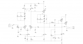
The output device could be a MOSFET, a tube, or an NPN. I use high impedance Sennheiser headphones, so the tube output would probably work fine for me, but I suspect the MOSFET or NPN output would have lower distortion. With a negative high-voltage rail, the output device could even be a 6AS7 (although that is getting a little bit impractical for a headphone amp, assuming you want it to be compact).
Note that these 2 attachments are conceptual schematics, drawn to emphasize the direct coupling. I posted a more practical version on the “downloads” page of my website, with a modified circuit to control DC offset, along with the required DC offset protection circuits.
Downloads – Tavish Design
I haven’t built it yet, but I’m planning to develop a PCB and build it soon. Any suggestions before I do? I assume there are similar circuits out there? How much current is really needed for low impedance headphones? Is there a better output MOSFET than the IRF540? Thoughts about an NPN (or Sziklai) output version? And note, this basic topology could be used to build a direct-coupled hybrid power amplifier as well.
Scott
Attachments
I came here from your other thread. I personally am more interested in hybrid power amplifiers than headphone amps, so I'm looking at the circuit form that perspective.
I think the level shifters are a good idea, even if not new. For a power amp, one issue with your ckt might be gain. A power amp needs ~20dB gain and you probably want 20dB NFB. But the single tube differential pair will not give 40dB gain, even with the current-mirror load.
What output stage did you have in mind for a power amp?
Iwan
Hi Iwan,
Thanks, I think that's a good point - with a single tube gain stage, there is limited loop gain in the amp. I plan to experiment with the stage to see how much gain is possible, but with a 12AX7 and a current mirror load, 35 dB seems reasonable. That would leave about 15dB for feedback, and 20 dB for the gain of the amplifier. If the output stage is sufficiently linear, that might be OK. Many tube amps work with well 15 dB NFB (or even less).
Adding another gain stage would make things much more complicated and detract from the elegant simplicity, I think.
I think the topology would work with almost any single-ended or complementary output stage. For a headphone amp, any of the single-ended stages I showed would work well.
For a very simple hybrid power amplifier, a complementary MOSFET output stage is appealing, since the MOSFETs don't need safe operating area protection. But MOSFETs have low gain and are less linear than BJTs, so one possibility would be a complementary output stage with BJT-MOSFET complementary feedback pairs.
The CFP output stage is quite linear, so it might not need a lot of feedback, which might make it a good choice, given the limited loop gain.
Scott
- Status
- This old topic is closed. If you want to reopen this topic, contact a moderator using the "Report Post" button.