Sorry guys for not posting for a looooong time! I think the schematics are perfect, but I didn't have enaugh money to finish it sadly 
I have spent my last half year learning about electronics to get back to it better, and at the same time, I ran out of money (I was moving from one place to an other, and had to buy furnitures and stuff).
I Really hope none of you really tought I left you guys, and if someone would like to continue the thread, feel free, since this amp has got potential!
I will just have to stay ready to have money...
Cheers, and I hope we will be continuing!
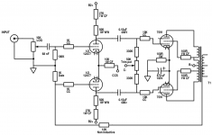
I'm interested in possibly reviving this thread. I've cobbled together a schematic of the various versions that are spread through this thread and have attached it below.
The main difference is that I'm looking to build a pair of monoblocks. I have a set of Bogen CHB-35a chassis that are going to act as donors, which means I've got a number of 7868s to use.
I'm currently based in the UK, so was looking to source some local 'iron' on a budget. I've come across these folks:
'Vvt Ltd' design and make Wound Components including Transformers, Chokes and special Coil Winding.
who seem like they'll fit the bill. I was thinking of their VTH13332 for the mains and the VTL14663 for the choke. For the OPT the only one I could find that might be suitable would be the VTP13135, but it seems like it's not going to provide a whole lot of headroom. Any suggestions? (I like Edcor, but they're pretty pricey over here...)
It will probably not be a speedy process, but I figure this is as good a place as any to start. Are there any comments?
Attachments
Yes, that looks like it would be perfect. Thank you!
Do you have an o'scope? If so, you can tweak NFB phase compensation "perfectly". OTOH, a brute force method is available for someone with minimal instrumentation. Connect the speaker side of R26 to ground via a 150 pF. mica or NP0 (C0G) ceramic capacitor. The cap. shorts the NFB loop out above 80 KHz. and the natural roll off of the "iron" will set in.
Hm. Interesting. The only thing I would be worried about is space on the chassis and fitting it into the existing shells. I'm OK with moving things around and drilling new holes, but I would like to keep the form-factor the same. I will have to measure the chassis when I get home.
These photos aren't mine, but it's representative of the amount of space I have to work with:
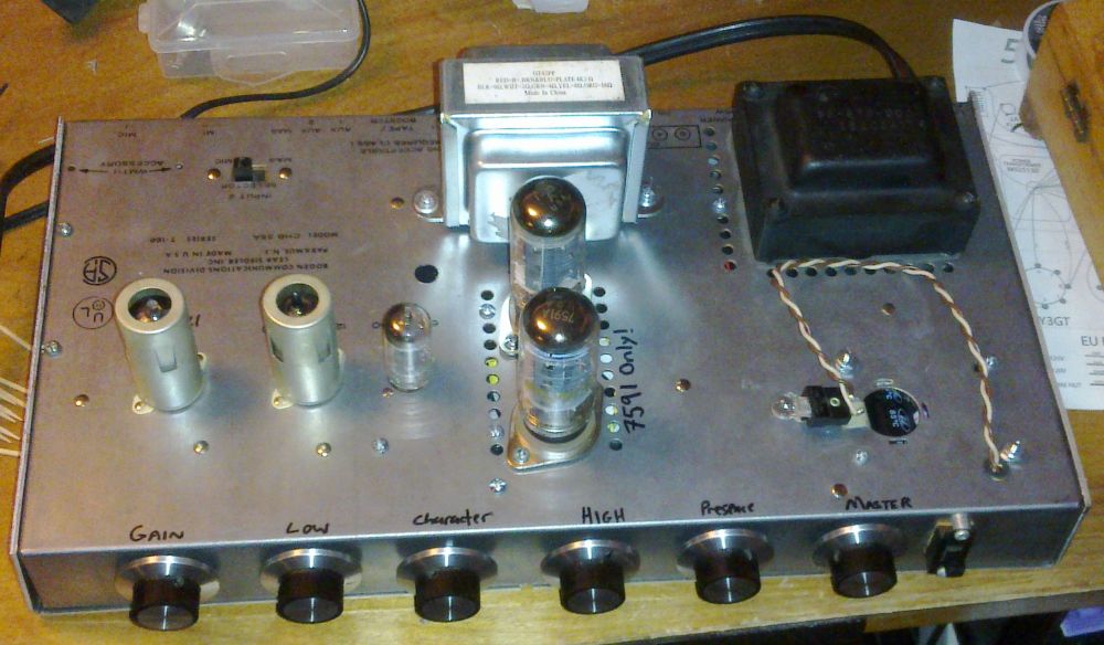
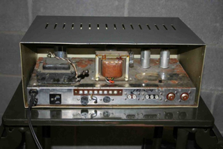
These photos aren't mine, but it's representative of the amount of space I have to work with:
ahankinson, according to your last PDF, your schematic is incorrect. On the 12AT7 grid to ground resistor, it shouldn't be 140k but 100k. I am getting money to slowwwwwwly restart building the amplifier
Also, I gathered everything together to have a place where are the latest schematics together.
Eli, thank you for taking care of me and instructing me while designing this amp... It helped me a lot, and after these years, I feel my knowledge confident to start THINKING instead of just drawing
Also, I gathered everything together to have a place where are the latest schematics together.
Eli, thank you for taking care of me and instructing me while designing this amp... It helped me a lot, and after these years, I feel my knowledge confident to start THINKING instead of just drawing
Attachments
I am getting money to slowwwwwwly restart building the amplifier
Also, I gathered everything together to have a place where are the latest schematics together.
Sebastian, this is great news! I enjoyed your posts, and Eli’s tutoring, as well as rongon and other contributors. I hope this project will continue and end with your amplifier singing beautiful music.
Well, after several years, and changes in houses, jobs, and countries, I'm finally ready to get back to this. I still have my old Bogen PAs that I intend to make into monoblocks with this circuit.
I have read and re-read this thread, and have assembled a schematic that has annotated voltage expectations, etc. I can share that later. I'm now working on specific parts so I can put together an order for the transformers, and I have a few questions.
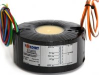
I believe the Hammond 373CZ power transformer would be my first choice, since it is a drop-through that I can probably use with a bit of modification on the current chassis.
Hammond Multi-Tap PRI, 159VA, 50/60HZ 373CZ, 131,99 €
This is a 325-50-0-325 on the HT winding. My intention is to use the 50v tap for the bias voltages. I have two questions about this:
1. The 50V bias tap is not a CT winding. Will the Millett "two taps" trick work with this? Or will it need to find something else? I'm also not entirely sure how it will work with the 6AL5.
2. I get an estimated 125ma current draw for two 7868/7591s and the 12AT7. The HT winding on the Hammond is 173ma. I know this will technically work, but is there enough overhead so that the PT is not stressed? (I would be more comfortable with a 200-250ma rating).
For the output transformers I believe I'm going with the Hammond 1650HA. I know these aren't "the best" but the intention is that these amps will be a tinkering platform, so they may find themselves upgraded to better iron at a later point in their life.
Hammond Audio Transformer 6.6K OHM 40 WATT 1650HA, 107,31 €
Finally, the choke I've chosen is the Hammond 159T:
Hammond Choke 159T, 23,06 €
If anyone's still watching and interested in this thread, I would appreciate your feedback!
I have read and re-read this thread, and have assembled a schematic that has annotated voltage expectations, etc. I can share that later. I'm now working on specific parts so I can put together an order for the transformers, and I have a few questions.
I believe the Hammond 373CZ power transformer would be my first choice, since it is a drop-through that I can probably use with a bit of modification on the current chassis.
Hammond Multi-Tap PRI, 159VA, 50/60HZ 373CZ, 131,99 €
This is a 325-50-0-325 on the HT winding. My intention is to use the 50v tap for the bias voltages. I have two questions about this:
1. The 50V bias tap is not a CT winding. Will the Millett "two taps" trick work with this? Or will it need to find something else? I'm also not entirely sure how it will work with the 6AL5.
2. I get an estimated 125ma current draw for two 7868/7591s and the 12AT7. The HT winding on the Hammond is 173ma. I know this will technically work, but is there enough overhead so that the PT is not stressed? (I would be more comfortable with a 200-250ma rating).
For the output transformers I believe I'm going with the Hammond 1650HA. I know these aren't "the best" but the intention is that these amps will be a tinkering platform, so they may find themselves upgraded to better iron at a later point in their life.
Hammond Audio Transformer 6.6K OHM 40 WATT 1650HA, 107,31 €
Finally, the choke I've chosen is the Hammond 159T:
Hammond Choke 159T, 23,06 €
If anyone's still watching and interested in this thread, I would appreciate your feedback!
Well, after several years, and changes in houses, jobs, and countries, I'm finally ready to get back to this. I still have my old Bogen PAs that I intend to make into monoblocks with this circuit.
I have read and re-read this thread, and have assembled a schematic that has annotated voltage expectations, etc. I can share that later. I'm now working on specific parts so I can put together an order for the transformers, and I have a few questions.
I believe the Hammond 373CZ power transformer would be my first choice, since it is a drop-through that I can probably use with a bit of modification on the current chassis.
Hammond Multi-Tap PRI, 159VA, 50/60HZ 373CZ, 131,99 €
This is a 325-50-0-325 on the HT winding. My intention is to use the 50v tap for the bias voltages. I have two questions about this:
1. The 50V bias tap is not a CT winding. Will the Millett "two taps" trick work with this? Or will it need to find something else? I'm also not entirely sure how it will work with the 6AL5.
2. I get an estimated 125ma current draw for two 7868/7591s and the 12AT7. The HT winding on the Hammond is 173ma. I know this will technically work, but is there enough overhead so that the PT is not stressed? (I would be more comfortable with a 200-250ma rating).
For the output transformers I believe I'm going with the Hammond 1650HA. I know these aren't "the best" but the intention is that these amps will be a tinkering platform, so they may find themselves upgraded to better iron at a later point in their life.
Hammond Audio Transformer 6.6K OHM 40 WATT 1650HA, 107,31 €
Finally, the choke I've chosen is the Hammond 159T:
Hammond Choke 159T, 23,06 €
If anyone's still watching and interested in this thread, I would appreciate your feedback!
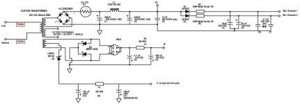
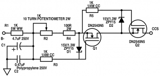
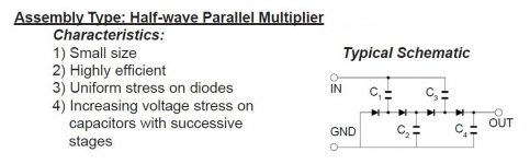
The 2 rails from 1 CT winding method will not work for obtaining multiple negative voltages from a 50 VAC bias tap. Instead, use multiple taps on a 1/2 wave parallel voltage multiplier. SS rectify the B+ and use the 2 A./5 VAC winding to feed the voltage multiplier. Tie the bias tap off.
The schematic provided is for positive polarity. So, turn the diodes around, to obtain negative voltages. Use Schottky diodes in the multiplier for lowest noise and smallest forward drop.
BTW, use the smallest valued 1st B+ filter cap. that keeps the rail voltage up. That method allows for squeezing a few extra mA. of B+ out. When cap. I/P filtration is employed, the full V/A capability of a rectifier winding can't be accessed. Charging pulse I2R heating is why. A smallish 1st filter cap. holds the heating down.
Attachments
- Home
- Amplifiers
- Tubes / Valves
- Choosing a tube amplifier to build, HELP needed