Ah, I was wondering what that was for. Seems very shoddy to me.
Sounds like Harlon is best off scrapping the whole thing and using the tubes and power trafo to build his own amp.
Very shoddy, indeed!
The power trafo, tubes, and sheet metal can be retained. I suspect the tube sockets are junk phenolic wafer, which should be replaced.
Monty,
The Philco is very much a "bottom feeding" setup. T3 is a mono push/pull bass only trafo. Notice that the otherwise identical T2 and T4 are phased 180o apart. T2 and T4 are small, which makes them incapable of handling bass. The setup is a grossly inferior, dirt cheap, implementation of the satellite/subwoofer concept.The thing rates lower than whale guano and that's on the bottom of the ocean.
The original console was at the very bottom of the product line.
Eli, don't hold back. Tell us how you really feel.
Just to clear the air, at least for my part in this, I do get that my little Philco is basically a total piece of garbage. Originally getting it up and running and then my Magnavox running has been a lot of fun and I've learned a ton. In the process of fixing the Magnavox I had to canabilize some critical parts from the Philco.
It's up for another rebuild and I figured, hey, why not go for the little piece of junk on steroids approach. As a teenager I had an 81 Ford Fairmont that I dreamed of stuffing a 302 crate motor into, creating a very powerful piece of junk.
This Philco rebuild is basically the same concept.
Believe me, on more than one occasion through this process I've considered that with the money I'm looking to invest in this "bottom feeder" I could potentially scratch build something really nice or make some real quality upgrades to my Magnavox.
Thanks to those who have helped through the process thus far. Who knows maybe in the end I'll just replace the missing bits on the Philco and spend my money more wisely. The "maggot-box" is easily 20 times the stereo.
Thanks,
Harlon
Harlon, if you invest your time into improving this then it will be wasted as the result will be worse than if you completely dismantled the Philco and used the valves and power transformer to build something good.
There's an expression 'do it nice or do it twice'. I prefer to do it nice and end up with a really nice end result that I know was 100% my own work .
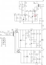
I'd highly recommend this circuit (attached) if you want to build the best EL84 SE amp possible. If you want to you can use the 6CA4 rectifier with a CLC filter to produce the B+ but you might need a second transformer tap. But really you don't want to be using old transformers. Can you hear it buzzing when it is switched on, however quietly? If so bin it!
There's an expression 'do it nice or do it twice'. I prefer to do it nice and end up with a really nice end result that I know was 100% my own work
.I'd highly recommend this circuit (attached) if you want to build the best EL84 SE amp possible. If you want to you can use the 6CA4 rectifier with a CLC filter to produce the B+ but you might need a second transformer tap. But really you don't want to be using old transformers. Can you hear it buzzing when it is switched on, however quietly? If so bin it!
Attachments
Sounds like Harlon is best off scrapping the whole thing and using the tubes and power trafo to build his own amp.
In the end that's what it looks like. I planned on replacing the tube sockets as well. Unless I just go for the simple replacement of what's now missing, a rebuild will require a new chassis. I'm fairly certain there isn't enough room for a choke and new O/P iron with the existing hole layout. Cleaning out the tone and balance pots will make some room but probably not enough.
At what point does it lose it's Philconess and become something else?
Please Humor Me: One Last Dumb Question
I'll admit my stupidity on the front end so please view these as purely academic questions.
Lets say I'm an idiot with more money than brains and I want to upgrade all the iron on my whale guano amp.
Real questions:
When upgrading power transformers with new iron what are the important figures to look for when picking a new unit? I'm assuming the 3rd, 4th and so on filaments need to more or less match. 6.3v at X mAmps and so on. For the secondary main power section can you go too high on mAmp rating? and how close do I need to stay to the 190/380 voltage rating? The Trafo on old whale guano is 190/380 volts at 105 mAmps. Would something at 220/440 at 300 be going too far?
Thanks for sharing the knowledge.
220/440 would be too far as it would put excessive plate voltage on your 6BQ5s
A transformer that would be ideal for what you want is the EDCOR XPWR146. If you use a CLC filter with the first capacitor off the rectifier being 47uF then you will lose the extra 10V no problem. You will also get a great reduction in hum.
Have a look at my EL84 SE schematic.
A transformer that would be ideal for what you want is the EDCOR XPWR146. If you use a CLC filter with the first capacitor off the rectifier being 47uF then you will lose the extra 10V no problem. You will also get a great reduction in hum.
Have a look at my EL84 SE schematic.
I always look for value. This AnTek toroid will be difficult to better. You get all sorts of leeway for experimentation. For instance: SS rectify the B+, wire all signal tube heaters to 1 filament winding, and voltage multiply the 2nd filament winding to obtain a bias (C-) supply.
BTW, toroids exhibit wide bandwidth. Therefore, put ferrite beads on the primary wires to prevent crud riding on the AC mains from getting into the amp.
BTW, toroids exhibit wide bandwidth. Therefore, put ferrite beads on the primary wires to prevent crud riding on the AC mains from getting into the amp.
A transformer that would be ideal for what you want is the EDCOR XPWR146.
No disrespect, but would a XPWR135 provide a more plug and play option? With it's dual 200 and 6.3 volt leads. Not sure how to wire the single hot lines coming out of the 146.
Have a look at my EL84 SE schematic.
I did take a long look. Unfortunately, my experience thus far with power supply and amp topology is limited to whale guano and a Magnavox 9304-20. They are simplistic to say the least in comparison. Part of the reason I've been so hesitant to add solid states bits to my toolkit is that I've not yet mastered understanding of tube technology. Don't want to confuse the works. Hopefully I'll get there in the near future.
Or the ESP site, that would be a very good place to start as it's audio oriented and the author doesn't talk a lot of rubbish about audiophool nonsense that a lot of valve articles seem to.
Valves Index
Valves Index
A Couple Learning Questions: Amplification Class and Biasing?
Spent some time reading since we last discussed this amp. Have some questions.
Amplification Class:
As it lives in its present configuration, is Whale Guano a Class A, AB or B amplifier? I think that it is class a because with the 2 EL84s driving half the signal from the 12ax7 to create stereo continually they are always "on." Would it be correct to say that the amp isn't really in a push pull configuration. It seems more like two non parallel single ended outputs. Because of this configuration is the amp limited to class A output?
Biasing:
Again, Whale Guano currently. WG is cathode biased. It has an electrolytic bypassed cathode resistor regulating current on the cathode of the pair of EL84s. Monty, the CCS biasing you have suggested. Would this be a variation on cathode biasing where basically the bypass capacitor is replaced or augmented by the CCS. Am I correct that in these two methods of biasing the voltage used to bias the cathode is pulled off the cathode itself and stored in the CCS or capacitor respectively? Do you prefer the CCS/regulator because it provides more consistent voltage management to keep the Cathode to Grid voltage differential more stable?
You're right. It is a class A design. It's in a push pull configuration for the bass and single ended for each channel.
The bypass capacitor is not replaced by a CCS, if it was then the circuit would have no gain. It's a CCS with AC bypass via a capacitor so the DC impedance is very high (CCS) and the AC impedance is very low (capacitor). This configuration with the CCS ensures the anode/cathode current remains stable throughout the valves life.
The bypass capacitor is not replaced by a CCS, if it was then the circuit would have no gain. It's a CCS with AC bypass via a capacitor so the DC impedance is very high (CCS) and the AC impedance is very low (capacitor). This configuration with the CCS ensures the anode/cathode current remains stable throughout the valves life.
You're right. It is a class A design. It's in a push pull configuration for the bass and single ended for each channel.
So with that said it is Class A? From what I've read SE amps can only perform as Class A amps.
Not in relation to Class, but in relation to the design would it be fair to say that WG is cheating stereo out of what would best be configured as a parallel se or true push pull mono amp? If configured as a pp-mono it could be designed to run into Class AB or B, correct?
The bypass capacitor is not replaced by a CCS, if it was then the circuit would have no gain. It's a CCS with AC bypass via a capacitor so the DC impedance is very high (CCS) and the AC impedance is very low (capacitor). This configuration with the CCS ensures the anode/cathode current remains stable throughout the valves life.
Would it be fair to say that the CCS augmented cathode bias is an improved variation on standard cathode biasing? Dumb question, wish I hadn't asked it.
Generally, is the CCS cathode bias similar to a fixed bias in effect? Seems that the more stable anode/cathode current yielded by using the CCS would be similar in effect to having a set line current as in a fixed bias? Are there particular benefits to using one over the other?
Yep, CCS biasing is better because when you are using either a cathode resistor or negative grid bias then you are making the bias point dependent on the valve (which will change throughout it's life), less so with cathode resistor biasing but for an LM317 CCS you only have to add one component (the 317) so it seems silly not to.
CCS bias is a fixed bias, it won't change (by it's nature) with changes in anode voltage, which makes things a lot easier .
SE amps are always class A, PP amps can be either class A or class B.
CCS bias is a fixed bias, it won't change (by it's nature) with changes in anode voltage, which makes things a lot easier
.SE amps are always class A, PP amps can be either class A or class B.
Parallel SE vs. Push-Pull Mono: Preference or Practicality?
I'm assuming that when designing and building a new amp that choosing a SE or PP mono block topology is mostly preference as to what quality audio
reproduction and amplification you're aiming for.
My understanding is that quality of speaker is also a factor. The speakers I have available for usage with WG are mid 60's console speakers from a SS Motorola. My guess is that they won't stand up to a SE amp. With these as the speakers currently available to me would I be better off leaning toward an improved PP design for my Whale Guano rebuild?
Sidebar question, is the generalized disdain aimed at the existing combo SE PP design of WG because it is doing too much with too little and doing none of it well? Does good sense say to do one thing and do it well?
Last edited:
Revisiting the old Philco
Eli and Monty,
I had to set my amps aside for a time, I'm just getting back to put some the things you guys helped with to work.
I'm basically looking at making the clc changes to the ps and then upgrading the op trafos and possibly the power trafo as discussed previously. Cutting out everything but maybe the volume control. Fundamentally starting over at the tubes.
I'm looking for schematic/topology recommendations.
6ca4 - rectifier
12ax7 - preamp
(2)el84 - power
Wondering if an 8601 would work
Thanks for the PM, always willing to help . Even more willing to deride, though !
Sod the tube rectifier, go in for 2 1N4007. If you have excess voltage on the B+ because of this, drop the excess voltage across the resistor in the CRC filter in the power supply. Gives you a bit more hum reduction. You can also increase the filter capacitor values if you use a solid state rectifier which will further reduce hum. Don't forget to tap those AC heaters to ground as well.
Hope that helps, dude.
. Even more willing to deride, though !Sod the tube rectifier, go in for 2 1N4007. If you have excess voltage on the B+ because of this, drop the excess voltage across the resistor in the CRC filter in the power supply. Gives you a bit more hum reduction. You can also increase the filter capacitor values if you use a solid state rectifier which will further reduce hum. Don't forget to tap those AC heaters to ground as well.
Hope that helps, dude.
- Status
- This old topic is closed. If you want to reopen this topic, contact a moderator using the "Report Post" button.
- Home
- Amplifiers
- Tubes / Valves
- Philco K1629 Upgrade Options