The review for the 859 amp from HIFi News is attached. The circuit diagram is included.
View attachment Paravicini.pdf
View attachment Paravicini.pdf
Karl,
I dealt with Dena Ross.
best
tim
Thanks for the reply, but who or what is Dena Ross, google did not provide any answer?
Regards,
Here is the 859 schematic
https://www.diyaudio.com/forums/tubes-valves/66598-look-ear-859-pictures.html#post3373269
I think we must be talking about different amplifiers as the 859 input is a cascode.
510K is the plate load for the cascode as the pcc88 is run in "starved current mode"---I think it is called.
Starved current mode is unusual I understand but apparently (way over my head) it works very well.
I built mine (both 859 and 869) P2P rather than using a pcb but the circuit works well and is very sensitive so either your board is wrong or we are talking about different amplifiers.
Email me if you think I might be able to help in any way.
Bill--I understand you have other calls on your time these days so having a list of to do projects is understandable.
The second triode in the cascode does have a 510K plate resistor, however, I was referring to the descrepency between the schematic and the resistor of the first triode's plate, which is called out as 120 ohm, but is in fact, 1.2K on both boards.
"1.2K is the plate resistor value (actual), though the schematic calls out 120 ohms."
The 1.2K is not the load for "the first triode's plate". The upper tube's cathode is the load.
The low gain issue likely lies elsewhere.
I don't mean to be unkind but perhaps your lack of understanding and confusion about the circuit makes me think that the customer maybe justified in wanting his money back.
If your task was simply to install the new pcb then you have done that. If it was to install the pcb and get it working correctly then that hasn't happened--from what you say.
tim
"1.2K is the plate resistor value (actual), though the schematic calls out 120 ohms."
The 1.2K is not the load for "the first triode's plate". The upper tube's cathode is the load.
The low gain issue likely lies elsewhere.
I don't mean to be unkind but perhaps your lack of understanding and confusion about the circuit makes me think that the customer maybe justified in wanting his money back.
If your task was simply to install the new pcb then you have done that. If it was to install the pcb and get it working correctly then that hasn't happened--from what you say.
tim
Where did all that come from? I merely noted that the resistor value on the boards differed from the values on the schematic. Obviously there were other problems with the new board, such as high distortion in the left channel and a 60Hz hum. The voltage measurements between left and right channel were off by 30%. So something's wrong in there, but I wasn't going to do a part by part analysis to figure it out.
My question is how much gain is to be expected. I've seen cascode amplifiers used in early Fisher tube tuners, so I'm familiar with the concept and how they work. One simply doesn't expect a new PCB from the factory to be defective or improperly built. That's a risk the customer took and unfortunately, he got stuck in the middle.
as I said :
while we are there:
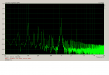
THD
ignore everything left of 1K
measured on example I made some TLC : 0.8Vpp to 28Vpp = 30.88db
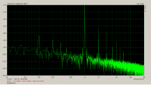
while we are there:
THD
ignore everything left of 1K
Attachments
Mark Mark Mark.....
I merely quoted what you had written and what you write reveals your level of knowledge.
Statements like "Well, if I look at that schematic, there's no way in heck that it's going to have that kind of gain" doesn't help your case.
And "Frankly, I'm not surprised it takes 7Vrms to make full power, given the fact that most of the amplifier is cathode-driven and the last stage is driven by the screen grid instead of the control grid" is also revealing.
And I have offered to try and help you where I can.
Not because I'm expert but because I have built two versions that worked as expected.
The obvious question is; what did the EAR factory say when you advised them that the board was faulty?
Did you do that obvious thing?
I don't mean to be unkind
I think it is just a matter of a very unfortunate choice of a nick

it was my unfortunate plastic interface box and most likely too close mains cable , while I've been tired of fighting with damn EMU1212 control panel

Mark Mark Mark.....
I merely quoted what you had written and what you write reveals your level of knowledge.
Statements like "Well, if I look at that schematic, there's no way in heck that it's going to have that kind of gain" doesn't help your case.
And "Frankly, I'm not surprised it takes 7Vrms to make full power, given the fact that most of the amplifier is cathode-driven and the last stage is driven by the screen grid instead of the control grid" is also revealing.
And I have offered to try and help you where I can.
Not because I'm expert but because I have built two versions that worked as expected.
The obvious question is; what did the EAR factory say when you advised them that the board was faulty?
Did you do that obvious thing?
Fine. My area, is more in the realm of OTL and RF tech. The Cascode is the only gain producing stage (or should have been) in that amplifier. The rest is a buffer and a screen grid driven output, which again, is very low gain.
I have not received a reply from the factory. But the customer said he returned the board. I told him I would do the board swap at no charge as a gesture of good faith, but he went and did it himself, which raised suspicions that perhaps he doesn't want me to compare the results.
It's still quite curious as to what could be wrong with the new board that could cause a simple cascode not to have gain.
it was my unfortunate plastic interface box and most likely too close mains cable , while I've been tired of fighting with damn EMU1212 control panel
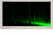
I figured this out, but the right side of 1kHz does not look too rosy either. Unless the amp is meant to work up to 1W.
remember what's measured ....... commercial SE tube amp of 12 declared watts
believe me , it holds , sonically, its own versus plenty of commercial drek , in spite of measurements (count that weed carpet down on lower levels is my sloppy setup , but harmonic peaks are logical and real)
TdP is Old Devil .....
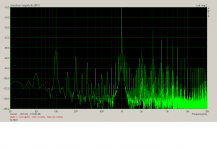
believe me , it holds , sonically, its own versus plenty of commercial drek , in spite of measurements (count that weed carpet down on lower levels is my sloppy setup , but harmonic peaks are logical and real)
TdP is Old Devil .....
- Status
- This old topic is closed. If you want to reopen this topic, contact a moderator using the "Report Post" button.
- Home
- Amplifiers
- Tubes / Valves
- Audio Note Kageki vs. EAR 859 vs. Audio Innovations: The First