I'm starting a new project with GU50 tubes so I'll post as many pics as I can about it. Hope you like it and most of all I apreciate your opinions , advices and so on... ")
I'm already finishing wooden chassis

Already finished and tried new output transformer R aa=4k, sec. 4/8 ohm


I'm already finishing wooden chassis
Already finished and tried new output transformer R aa=4k, sec. 4/8 ohm
Last edited:
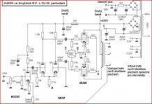
It will be this one http://hlava.webpark.cz/Dvojcinne/sch2x50wGU50.GIF
Last edited:
The screen grid voltage arrangement of GU50's is not optimal.
According to my tests the optimum voltage is about 350 V and the current supply needs to be up to some tens of mA's.
In your circuit there is 56k 5 W series resistor from +Ub line to form the Ug2. This is high impedance.
Also the screen grid resistors should be lowered to max. 1k. Otherwise you wont't get max. available output power.
I have used NFET regulator to form the screen voltage to GU50 PP (attached).
Attachments
The screen grid voltage arrangement of GU50's is not optimal.
According to my tests the optimum voltage is about 350 V and the current supply needs to be up to some tens of mA's.
In your circuit there is 56k 5 W series resistor from +Ub line to form the Ug2. This is high impedance.
Also the screen grid resistors should be lowered to max. 1k. Otherwise you wont't get max. available output power.
I have used NFET regulator to form the screen voltage to GU50 PP (attached).
I noticed that as well.
The difference in g2 current between idle and full power is something like a factor 5. You need a low impedance source here.
The bias pots seem to be a little high: 300k where the gridleaks are only 110k. Changing bias will change the input impedance a lot.
I agree...the final's g2 supply can be improved. Not to mention the single-C filtering for the plate supply. A simple regulator consisting of a power MOSFET with its gate hung off a voltage divider of appropriate value( say in this case 350V ) will work well. Then 1k stoppers on each grid. Use an enhancement mode, FQP2N90 and don't forget the gate clamp Zener... Shunt its source to ground with some resistance in order to drive more current through it and increase its gm( and therefore performance ).
cheers,
Douglas
Shunt its source to ground with some resistance in order to drive more current through it and increase its gm( and therefore performance ).cheers,
Douglas
thank you for help so far, now Im taking care of chassis to be done but need to get some more things.
There will be mV meter and four position switch on the front panel to bias all output tubes easily and behind each tube will be trim pot... just have to get those with very short shaft with cutout for screwdriver , didnt find any on ebay
There will be mV meter and four position switch on the front panel to bias all output tubes easily and behind each tube will be trim pot... just have to get those with very short shaft with cutout for screwdriver , didnt find any on ebay
thank you for help so far, now Im taking care of chassis to be done but need to get some more things.
There will be mV meter and four position switch on the front panel to bias all output tubes easily and behind each tube will be trim pot... just have to get those with very short shaft with cutout for screwdriver , didnt find any on ebay
eBay user kwtubes has small metal cased Russian trim pots that might suit your use.
The downside is that they usually come in boxes of 50, but they are very cheap regardless.
I have purchased from him and have been happy with the quality.
Already got NOS caps 250uF/500V Tesla for power supply
An externally hosted image should be here but it was not working when we last tested it.
Last edited:
Already put some layers of a lacquer
An externally hosted image should be here but it was not working when we last tested it.
This is more or less how the things will be ... Still not sure about the caps.
An externally hosted image should be here but it was not working when we last tested it.
Already put some layers of a lacquer
An externally hosted image should be here but it was not working when we last tested it.
cool, do you considered some wood oil? Is this only a clear lacquer? Looks a bit darker- Status
- This old topic is closed. If you want to reopen this topic, contact a moderator using the "Report Post" button.
- Home
- Amplifiers
- Tubes / Valves
- GU-50 push pull amplifier