Good evening,
I have been slowly chipping away at a hum problem I've been having with an old power amp. I've come to a point where I think I may need more explanation on how grounding works in these old amps.
The amp in question is a TL-25 plus. It is a 250v amp that I'm running stateside on a step up transformer. I've been testing it on a single Wharfedale W60.
With the amp alone plugged in, I get quite a bit of hiss and slight hum. When I short the input to ground, the hiss and hum are substantially quieted. In fact, I have to put my ear next to the speaker to hear anything. From the tweeter I only hear hissing, but from the woofer I hear hissing AND hum.
The other bizarre thing that occurs is that when I turn the amp off, there is a buzzing sound that is louder than the ambient noise. The only way to describe it with letters would be: zzzz. It only occurs for a few seconds. (Something to do with cap discharge?)
The amp appears to be using a star grounding scheme. The tie point to the chassis is the bolt holding the bracket for the main filter can cap. The turret board looks to be using local nodes for the stage grounds, and then running wires to the bracket's bolt.
I suppose what I'm ignorant of is how this is supposed to work. I've read that signal, power supply and safety earths should be separate until tied together at a singular point on the chassis. In this amp, safety earth is also tied to the bracket bolt along with everything else. Should this be attached to the chassis at a separate point? Should the power supply grounds also be kept separate from signal ground until tied to a singular chassis point?
The Safety Earth does not need to be tied in at the same point/bolt as the Main Audio Ground.
I believe it is better to site the Safety Earth where it works best. At the mains power input socket.
Then locate the Main Audio Ground link to the Chassis where it too works best. This is usually not on a long wire back to the Safety Earth at the mains input socket.
There may be a transformer inter-winding screen. This will have a wire that needs to be tied to Chassis at the transformer, such that the screen wire is VERY SHORT, for lowest impedance.
This makes a total of three Chassis connections.
There should not be any need for more.
Temporarily disconnect the Main Audio Ground to Chassis connection. Measure the resistance from MAG to Chassis. It should appear as VERY high. If it reads low, then find the extra Chassis connection and move it to the correct location.
Last edited:
Chassis as an interference Screen
The Chassis is an Interference Screen.
As such it does NOT need a low resistance connection to the amplifier/s.
The other purposes of the Chassis are to support all the components
and
to keep you and your kids from harm, by inadvertently touching hot, or high voltage, parts.
Many parts of the circuit may make capacitive connections to the Screening Chassis. These will not cause hum, nor will they create noise.
They will help attenuate noise.
The screening Chassis is NOT part of the amplifier/s.
The amplifier/s will work perfectly well without the Screening Chassis.
Thanks for the response. Is the terminal marked 'II' on the power transformer primary supposed to be hooked to anything? It isn't on mine. I also don't have the AC outlets, which is where it appears on the schematic to run to?
Is this 'II' terminal the shield you were referring to? I'm hesitant to hook it to ground in case it damages the PT.
Is this 'II' terminal the shield you were referring to? I'm hesitant to hook it to ground in case it damages the PT.
Attachments
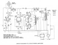
Look again at the sch.
The round symbol (bottom right) with the three circles/pins is the Mains Power input socket.
The shell is connected to the Chassis. This seems wrong to me. The third pin should be connected to the Chassis.
The third pin is connected to the amplifier's main ground.
The left circle/pin is connected to the fuse. This must be the Live. One always fuses the Live.
The right circle/pin is connected to the switch. This is the Neutral. Normally the Live is switched, or both are switched. This is unusual. The II symbol appears after the switch. This is the switched Neutral connection to the power output sockets.
DO NOT use the II for anything else. IT IS MAINS POWER !
I note that this is a USA model. The 240Vac model may be wired differently, certainly we tend to use two pole mains switches, but maybe not way back then.
If this was mine I would be looking at changing the switch and ensuring that PE went direct to Chassis, to bring it up to modern standard.
- Status
- This old topic is closed. If you want to reopen this topic, contact a moderator using the "Report Post" button.