I have 355V plate voltage and output iron is 8k:8R no global feedback.
Screens tied to plates through 100 ohm resistors.
Cathode bias, shared 360R common resistor, fully bypassed w/ 1000uF cap.
I have plenty of drive but I see clipping at 7V into 8 ohms. I thought I would get more closer to 10-12 watts not 6
I have tried different tubes so they are not the problem.
Thoughts?
-bird
It could be because you have screen resistor to anode.
If I remember correctly you don't get as much power in triode mode.
I had a look at one of my old designs and I have put the screen through 1K to the B+.
This is pentode mode.
Another mode is ultra linear where the screen goes through ha resistor to a 40% tap on the output transformer.
If I remember correctly you don't get as much power in triode mode.
I had a look at one of my old designs and I have put the screen through 1K to the B+.
This is pentode mode.
Another mode is ultra linear where the screen goes through ha resistor to a 40% tap on the output transformer.
Last edited:
I have 355V plate voltage and output iron is 8k:8R no global feedback.
Screens tied to plates through 100 ohm resistors.
Cathode bias, shared 360R common resistor, fully bypassed w/ 1000uF cap.
I have plenty of drive but I see clipping at 7V into 8 ohms. I thought I would get more closer to 10-12 watts not 6
I have tried different tubes so they are not the problem.
Thoughts?
-bird
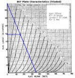
Loadline (attached)
Given what you've told us, 10-12W is unrealistic here. The value I get for output is 9.49W. Given the I2R and core losses in the OPT, and the use of cathode bias (always costs some output watts) I'd say 6W of output isn't too far out of line here.
If you want more output, you'll have to go with pentode operation.
Attachments
I do have a driver capable of AB2, it's Pete Millets board: A2 Buffer
I need a negative supply for this to work. Is there any problems with paralleling rectifiers? What I am asking is it okay to take say a 1N4007 and wire it's cathode to pin 6 of the rectifier tube (5Y3GT) and it's anode to a voltage divider or zener string to get my negative rail? The amps normal power supply caps will get charged through the tube rectifier on the positive cycle of that HT tap, the negative cycle will charge the cap at the voltage divider through the 1N4007 for the negative rail?
I will say with 103db sensitivity speakers the power is sufficient as is, I just thought I calculated something closer to 10 watts. I will try and do all the math out again to be sure, if it's correct then I might live with it. BUT I am tempted to try Pete's board and drive them into AB2.
Given what you've told us, 10-12W is unrealistic here. The value I get for output is 9.49W. Given the I2R and core losses in the OPT, and the use of cathode bias (always costs some output watts) I'd say 6W of output isn't too far out of line here.
Hi Miles, I think you are correct, now that I am thinking about it when I was starting this project I planned on using sand rectification, essentially giving me a much higher B+, I think it was around 420Vdc, that would have given me closer to the 10 watts.
Loadline (attached)
Given what you've told us, 10-12W is unrealistic here. The value I get for output is 9.49W. Given the I2R and core losses in the OPT, and the use of cathode bias (always costs some output watts) I'd say 6W of output isn't too far out of line here.
If you want more output, you'll have to go with pentode operation.
Loadline must be for 4 k/phase.
No. OPT is 8k, then one halve of OPT represents 2k, i.e ¼ of total impedance.
LTSpice shows the following values:
- Ia = 36 mA, then anode dissipation is below 12 W.
- Pout to 8 ohms is 6,8 W and to 4 ohms 8,5 W (from 8 ohms tap).
When increasing the tube current, output power does not increase, which is obvious.
The only solution to get more power is to increase supply voltage essentially.
With 450 V as +Ub the power output to 8 ohms is 11,6 W and to 4 ohms 14,6 W.
THD is very low in both cases, less than 0.2 %.
Last edited:
Ppp=2Pse...
No.
Power output of PP output stage can be many times bigger that 2 x output power of SE-stage.
No.
Power output of PP output stage can be many times bigger that 2 x output power of SE-stage.
I'm talking about class A. You are talking about AB.
I do have a driver capable of AB2, it's Pete Millets board: A2 Buffer
I need a negative supply for this to work. Is there any problems with paralleling rectifiers? What I am asking is it okay to take say a 1N4007 and wire it's cathode to pin 6 of the rectifier tube (5Y3GT) and it's anode to a voltage divider or zener string to get my negative rail?
Look at the Tubelab SE schematics at how he gets the negative voltage. It's similar to what you are talking about.
When increasing the tube current, output power does not increase, which is obvious.
The only solution to get more power is to increase supply voltage essentially.
With 450 V as +Ub the power output to 8 ohms is 11,6 W and to 4 ohms 14,6 W.
THD is very low in both cases, less than 0.2 %.
Hi artosalo, you are correct, and it all makes sense to why now I am seeing 6.5 watts. Originally I was going to use a bridge rectifier giving me B+ around 420v, so 10 watts was the intent. The power transformer had a 5V tap and the chassis already had a hole cut for an octal socket so I used a 5Y3 rectifier. Maybe I will try a 5AR4 or a 5U4GB, can't remember which has the lowest plate resistance, I am thinking it's the 5AR4.
Look at the Tubelab SE schematics at how he gets the negative voltage. It's similar to what you are talking about.
Hello wicked1, Good eye
 That is exactly (or close) to what I was thinking of doing. I think I was intending half wave rectification which would have been harder to smooth the ripple. If George uses this technique then it's good enough for me
Loadline must be for 4 k/phase.
The 4K/phase value would apply if he were in Class A. He already told us it's a Class AB design.
Class A: balanced two phase system where load resistance splits between phases.
Class AB, B, C: unbalanced two phase system where one phase cuts off and "disappears" leaving just half the primary active. Load per phase is divided by 4.
This is why a junk box OPT for Class A 6L6s had a Zpri= 4K4 : 4, 8, 16, 32, 125, 500R multi-tap secondary. (Also had ideal Z-transformation that was ideal for matching to Class AB 6BQ6GA finals even if it was a bit thin so far as power handling was concerned.) For Class AB 6L6s, OPTs usually have Zpri= 6K6.
- Status
- This old topic is closed. If you want to reopen this topic, contact a moderator using the "Report Post" button.
- Home
- Amplifiers
- Tubes / Valves
- 6L6 Triode AB Push/Pull Pout