I don't know - based on your picture, I'm wondering 1 and 7 don't go to the grids, with 2 and 6 being the common connection to bias. I am sure if you contact MM, Ward or Yves would be more than happy to confirm to you which is most correct. In simplest terms, you want to ensure the instantaneous polarities are in phase between plate and following stage grid. You can get it to work with incorrect polarity, but the high frequency phase shift will likely get really wild, and it should be easy to see on the scope.
So give these IT's a chance; perhaps they aren't hooked up correctly at first try.
So give these IT's a chance; perhaps they aren't hooked up correctly at first try.
It would be PP to SE...and I would like to use the Monolith above instead of buying another pair...
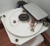
Zigzagflux...yes, I send Ward a mail with the scan above...to be clear: The hand drawing with the definition where the bias has to go to came from him or Yves, it was part of the delivered documentation.
Zigzagflux...yes, I send Ward a mail with the scan above...to be clear: The hand drawing with the definition where the bias has to go to came from him or Yves, it was part of the delivered documentation.
Last edited:
I am not sure you can do that with the bifilar Monolith. Ask the manufacturer...It would be PP to SE...and I would like to use the Monolith above instead of buying another pair...
I did...Yves told me that this is not possible...as well, his advise was to ignore the table, the drawing is the relevant piece of information. He told me to measure if phase is correct as this is a custom version, not documented. So I did...and yes, I have the right phase. Hmmm...now I need to re-think the idea of using one IT for both, PP...I have still a pair of LL1692A and LL1660AM...but not sure if those can ideally connected in a way in PP to SE that at least gain is staying the same, ideally a bit more. In the documentation I have found always only setups with reduced gain.
With the Lundahl you can do PP:SE. As as I said earlier they trade off performance at HF for flexibility. That's the only area you need to work on.
With the LL1692a you can certainly connect it as 1.75+1.75:1 (i.e. secondaries all in parallel) which is called ALT N connection or reverse the ALT V connection 1:75:2+2!
http://www.lundahl.se/wp-content/uploads/datasheets/1692A.pdf
Even if you have the 18 mA version the primary inductance will be 95H and 125H (for the reversed connection of course), respectively.
If you want to drive a 300B up to 200V peak-to-peak then try with 2+2:1.75. This will have 125H if 18 mA version or 240H if PP version. The latter would be better given the large amount of volts you will need to swing. Max oupt voltage won't be a problem.
Only things are:
1) HF performance
2) A PP driver that is capable of delivering 200V peak-to-peak with a total step-down of about 2.28:1.
Find yourself two pairs of 10Y or 801A and run them at 500V/25mA (about -40V bias)!
These in PP will also have about the recommended source impedance for smooth FR.
45, thanks for your ideas...I guess what I will do as a quick fix to test PP vs. SE: Use the IT as anode chokes and C-couple to the SE-Stage. The sound difference between Jupiter Caps and go full IT-Coupled is not dramatically IMHO...but I am using Silk-grid chokes in this setup, which might have as well an influence (to the better)...that way I should be able to use the Monolith ITs even for SE. The sound signature is a bit more clear, faster and tighter overall compared to the Lundahl...the Lundahl seem to have a more softer image overall, which might be what you want depending on your setup...their DC-resistance is as well double of the Monolith and the inductance four time more (LL1668Am anode choke PP).
The idea of PP driver for SE power stage has been used successfully in the past. Audio Tekne for example made a very compact (custom) 15W 845 SE using this kind of driver. This way they could also use their own typical permalloy transformers. The PP driver for the 845 was a 6350. A.T. amplifiers, despite the usual mystic presentation, are very solid and well performing amplifiers in all departments.
By the way: I recently read a small article in this book Audiophile Vacuum Tube Amplifiers - Design, Construction, Testing, Repairing & Upgrading, Volume 2 by Igor S. Popovich 2015-02-07: Amazon.de: Igor S. Popovich: Bucher
The author made some measurement on Interstage and line output transformers in realtion to their load. His findings:
When you use the IT without a Load resistor across the secondaries, just connect the grid of the next tube to drive:
- You have the highest amplification factor for the mid-range, but your bass response will suffer, in his example starting already at 150hz. The self-resonance peak of you IT is highest as well, hopefully outside of the audible band.
- If you start to use a load resistor across the secondary, bass response goes deeper and self-resonance is less...but you loose gain, for a full bass extension and no resonance in his example actual gain is reduce in half....
I guess I need to test this in my configuration ? Zigzagflux...you tested that for the IT-02 for sure already, right ?
Well, significant less gain gain at 150 Hz means only one thing: poor transformer or bad implementation. It happens when transformers are poor at low frequency for sure. If they have enough inductance the difference in gain between 30Hz and 1KHz will be negligible. Small at 20Hz. Of course PP has an advantage but some SE solutions work well too. Usual thing: design the circuit around the transformer and not the other way around!When you use the IT without a Load resistor across the secondaries, just connect the grid of the next tube to drive:
- You have the highest amplification factor for the mid-range, but your bass response will suffer, in his example starting already at 150hz.
I had not found the addition of burden to be a benefit in the design. The first stage operates so well relative to the driver stage, it can be considered absolutely perfect. Both freq resp and distortion.
The driver stage operates so well relative to the output stage it can be considered perfect, at least until 300B grid current begins. Both freq and dist.
Once grid current begins, the driver starts adding some distortion to the mix, but you really have to push it pretty hard. From a burden standpoint, the grid capacitance and effective resistance would far surpass any intentional burden resistor you would choose to install. So the resistors are unnneeded and add no real benefit.
Tubes quite enjoy feeding high impedance loads; keep it that way.
When dealing with non-bifilar xfmrs, I did find the burden interacted with xfmr strays, so perhaps if using a Lundahl or James or Sowter there could be some benefit. But I drove myself mad trying to pick R or RC burdens that would give flat FR. Gave up, went bifilar, problem solved.
May I ask for your opinion in a small detail: I am using currently only one negative supply for the CCS of both channels...this is the only place in a pire dual mono design where I did a compromise as I thought it will for sure not matter at all...right ? Or should eacc channel have its own negative supply as well ?
If it's a decent CCS, then sharing negative supplies should not affect performance. However, this will require each channel to have a shared common, which may be a source of ground loops. Depending on how you have handled the commons, it might just be better (easier) to keep them totally separate.
Zigzagflux/ Lynn, I have a quick question on the original Karna heating solution for the 300B...
Backround: I lost from the 10 Svetlana 300B I got, 3-4 in the last couple of months. Now I learned, that the Svetlana do not like DC-heating.
So, I would like to test this hypothesis and heat them with AC instead. I like the simplicity of Lynn's approach: No additional resistors (Which are in the signal path) for the electrical Centre Tap, just use the CT of the heater transformer.
Two questions:
- I would guess this would work as well if you put the cathode on earth, so no resistor to ground between CT of the heater and ground as I use fixed bias only at the moment ? CT of the heater goes directly (maybe a 10 ohm measurement resistor) to ground ?
- Is it important that earth is floating in this context, so no connection between earth of the circuit/CT of the heater transformer and ground of the power, plug, right ?
Lynn,
first please excuse my English, I am out of practise.
I know of your mentioned advantages in your pp design.
But I want to suggest an alternative, which should satisfy your demands.
Think of a Se 5687 driver stage at its voltage and wattage max, consisting of a 5687 current source loaded stage, no mu follower, connected via a cap to a se to pp interstage tranny. The other side is connected to the cathode, no cathode decoupling cap is needed. The tranny needs only a small airgap, no dc component. This means an high bandwith. Now use a pentode input stage like th E80F or a 6SJ7 at its sweet point of 1 quarter of B +. There would be almost no 2nd harminic which could interact with the Miller capacity pf your 5687 se driver. Use a not to high Ra.
Then sit down in your armchair and apply a huge amount of feedback from the 5687 plate to the input cathode. More than 40dB. Your driver tranny would see a vrry low Ri. Your input would have an extremly low input capacitance. The residual 2nd harmonics is in the order of your 2A3 driver. Use a B+ as high as possible. A cheap input tranny from pp to se is perhaps of advance if you want symmetric cables and further amplification.
What do you think of?
Frank
Backround: I lost from the 10 Svetlana 300B I got, 3-4 in the last couple of...
Nonsense !!!
For the last 16 years I have used only 2 pairs of = C = (not "S") Svetlana 300B with DC heating. DC heating is designed as a simple CVS for f + and ring-of-two CCS for f-.
I have never had any of the issues mentioned in the post above. But I ALWAYS used a Siemens medical power transformer for a very slow-turn-on.
I've written about this before in this forum, but I have to do it again. Sorry!
Attachments
Last edited:
It is true that some early Svetlana 300B tubes had a problem with DC on the filaments.
There can be uneven spacing from the filament wires to the two sides of the plate.
1.25 Amps DC makes each filament wire an electromagnet. And if the DC power supply is not soft start, or is not current limited, the cold filament has more than 1.25 Amps DC at start up.
There can also be an uneven spacing from the filament wires, to one side of the grid wires than to the other side of the grid wires.
With the above conditions, the failure mode is that one or more of the filament wires is attracted toward one side of the plate. As the filament wire moves, it then contacts the grid wire (now we have Zero bias).
That is what I, and others I know have had happen to us.
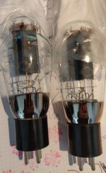
I have another pair of unused winged C 300B's in reserve. Bought in Moscow for about $ 15/pcs about 20 yrs before.
Tubes dealers are really screwing us, aren't they.
Excuse me, no replacement sales, no sales, no carnage, no exchange or anything.... or so.
Best diying for all
Tubes dealers are really screwing us, aren't they.
Excuse me, no replacement sales, no sales, no carnage, no exchange or anything.... or so.
Best diying for all
Attachments
Last edited:
- Status
- This old topic is closed. If you want to reopen this topic, contact a moderator using the "Report Post" button.
- Home
- Amplifiers
- Tubes / Valves
- Two driver options for 300B push pull