That would be an affirmative.
CCS versus resistor tail with capacitive bypass from B+ to cathode. Lynn Olson I am fairly certain is a proponent of the RC method. He may very well have results that are different than mine, so it is completely possible that my results have not been properly vetted. Or at least not gone through proper due diligence.
At the end of the day, I think which method one chooses is less critical than ensuring the transformers and triodes are optimized for their respective circuit requirements. Strays are extremely important when considering those push pull interstage transformers. Plate resistance and voltage swing, along with the next stage they feed, are critical to tube choice.
Well, if Allen Wright would be still alive, he would have a strong vote for ccs at the cathode as being the only real differential amp setup...I believe there have been some discussion on that in audioasylumetc....
Thanks for clarification what you meant with RC...makes a lot of sense...will also try both and see what happens...
Last question for the moment: You said you did the Tube-Reg/Ccs-Combo for each stage except the power-stage. Do you have the schematic of the psu of the power-amp ? I would like to understand better how you have the ccs in the cathode of the driver stages (the 46) working together with the ccs of the PSU before the tube regs...?
Thx so much ! Great learning experience ! I will follow your path shortly...by the way: Is there a difference in sound on reg tubes like it is with rectifiers and triodes ? Any preference ?
Sure. In looking at it, I guess it was only the first version that had a CCS/VR for the input stage. I removed it in the final version, since the plate load CCS did their job in removing hum (as expected and as discussed earlier).
The theory is fairly straightforward; the power supply 70 mA CCS provides fixed DC current absent any ripple to the devices that follow. The VR tube, of course, sets the static DC voltage conditions. The amplifier stage consumes a fixed 59 mA. This splits in the two 46 triodes based on their bias parameters. Matching here helps, but does not have to be perfect. Whatever remains (70-59=11 mA) must be running through the VR reg.
I don't notice any sound quality in the regulator tube choice, only silence. I purchased a boatload of NOS Russian regulators on eBay a few years back; they were cheap but seem reliable. Some fire better than others, which is probably the most important characteristic. The closer to operating voltage the firing voltage is, the better the stage operates at startup. It is the headroom taken by the 750 ohm resistor and CCS that can prohibit firing if the voltage requirement is too high. Keep in mind that once a regulator tube has been in operation for a few days/weeks, it tends to find a very stable and repeatable operating point, so it might pay to burn in a few and hand select good tubes.
Honestly, I prefer the purple ones because they look cool, but my Russian 0D3's ended up being orange. But they operate well, so that's what we have.
Last comment is that the VR tube does not see a highly dynamic current, it just consumes a very static 11 mA based on the power and cathode CCS governing the circuit around it. If I had a traditional SE stage, where current consumption varies with the music, the VR tube has to work a little harder to keep voltage static, and the benefits of solid state begin to prevail. For this specific topology, though, I think the VR tube is well-applied and cool-looking.
Attachments
Last edited:
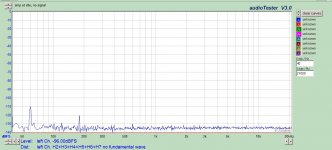
The only comparison that I was able to discriminate was measurement based. If I compared with my ears, there was not any discernible difference. The amount of hum at the speakers was very small without the regulator, such that it would not have been a problem. But when the regulator was in place, the measured noise floor was just so small, it was a beautiful thing.
There is the slight benefit of having a predictable idle condition when you know exactly what the B+ will be for that stage.
The 60/120 Hz you see in this is strictly due to the unregulated output stage; if I look at the driver stage output I am unable to measure any hum at all.
There is the slight benefit of having a predictable idle condition when you know exactly what the B+ will be for that stage.
The 60/120 Hz you see in this is strictly due to the unregulated output stage; if I look at the driver stage output I am unable to measure any hum at all.
Attachments
zigzagflux, I am just in the process to convert the interface of my pre-amp/Dac-output from SE to fully differential and seek a bit your guidance as I am not totally happy with the result...
Basis was a classic LTP with a CCS in the tail working into a LL1692A with two 4p1L as DAC-Output. When I configured the OPT as 1.75+1.75:2, the whole preamp is absolutely silent and very musical, transparent etc.
When I configure it to 1.75+1.75:2+2 I made the experience, that I have a slight hum/buzz and overall the overall music is more transistor like: It feels stiff, very stiff and less warm than if the opt is configure as SE on the secondary.
Now, I had a look on your preamp and power schematic again...and what I understand is thefollowing(please correct my understanding if I got something wrong):
- You configured basically your secondary of the ll1689 as one SE winding, but did not grounded anything on the secondary. So, no Ct of the sec. is grounded.
- You do not have a connection of ground between preamp and power amp, do you ?
If I recall right I think I have read that truely differential amps have two aspects to consider as well:
- PSRR of Diff.Pair is horrible (see Balanced-Ouput DACs and Tubes and Aikido)
- Diff. Pair / push-pull cancels 2nd Harmonic and add odd harmonics.
I guess both statements are right, that seems to be what I hear right now: The OPT configured with SE ouput cancels its power supply noise better out, while the balanced output seems to pass the noise further. The SE output and SE input preserves the harmonics better...?
I guess the first issue would be adress by a shunt reg, like the OD3. The second issue seems to stay with a LTP, so maybe I need to try your/Lynn's balanced topology....
Looking forward to your comments...
Last edited:
Sorry for the delay, been traveling the whole week.
Shielding of the XLR is solid grounded at the pre, and RC grounded at the power amp. Generally you want to ground your shield at the source, not the receiver. Silent as the grave.
Also, the Behringer output to preamp input is treated in similar fashion. Ungrounded output, center-tap grounded input with shielding as above.
My understanding is that power supply noise is a common mode signal, and therefore will be attenuated by the CMRR. Total PSRR is actually the sum of CMRR plus the circuit's attenuation of noise. So at the end of the day the diff pair has good PSRR, not bad, since CMRR is so high.
I would agree that even order is canceled and odd is added. It pays to use valves in diff pairs that have particularly low odd distortion, and you can almost ignore what their even distortion is.
I'm not too sure about that. Power supply noise should be independent of whether your output is two wire ungrounded or three wire center-grounded. More likely the issue is one of having grounding at both sides of the interconnect. Schematics might help, but for starters connect the output 2+2 and don't ground anything. Let the input of the power amp provide the grounding.
While a shunt reg is fun and works well, it sounds like a band-aid in this case, at least for now. You should be able to get a very quiet output even without regulation. You can add the reg later for that last bit of excellence, but something else is not correct IMO. Again, can you provide schematics?
Correct, the output of the preamp is two wire ungrounded. These two wires then feed via XLR to the power amp, which is grounded via the Cinemag input transformer. Effectively, the input transformer is acting as a balanced grid choke, if that even is a thing. I am not a fan of floating systems, power or signal, so the circuit is effectively grounded, but only in one location. Balanced circuits require equal impedance to ground, not equal voltage, so this is a very good quality balanced interconnect. The distance between preamp and power amp is over 10 feet, so there is good reason for a robust interconnect.- You configured basically your secondary of the ll1689 as one SE winding, but did not grounded anything on the secondary. So, no Ct of the sec. is grounded.
- You do not have a connection of ground between preamp and power amp, do you ?
Shielding of the XLR is solid grounded at the pre, and RC grounded at the power amp. Generally you want to ground your shield at the source, not the receiver. Silent as the grave.
Also, the Behringer output to preamp input is treated in similar fashion. Ungrounded output, center-tap grounded input with shielding as above.
If I recall right I think I have read that truely differential amps have two aspects to consider as well:
- PSRR of Diff.Pair is horrible (see Balanced-Ouput DACs and Tubes and Aikido)
- Diff. Pair / push-pull cancels 2nd Harmonic and add odd harmonics.
My understanding is that power supply noise is a common mode signal, and therefore will be attenuated by the CMRR. Total PSRR is actually the sum of CMRR plus the circuit's attenuation of noise. So at the end of the day the diff pair has good PSRR, not bad, since CMRR is so high.
I would agree that even order is canceled and odd is added. It pays to use valves in diff pairs that have particularly low odd distortion, and you can almost ignore what their even distortion is.
I guess both statements are right, that seems to be what I hear right now: The OPT configured with SE ouput cancels its power supply noise better out, while the balanced output seems to pass the noise further. The SE output and SE input preserves the harmonics better...?
I'm not too sure about that. Power supply noise should be independent of whether your output is two wire ungrounded or three wire center-grounded. More likely the issue is one of having grounding at both sides of the interconnect. Schematics might help, but for starters connect the output 2+2 and don't ground anything. Let the input of the power amp provide the grounding.
I guess the first issue would be adress by a shunt reg, like the OD3. The second issue seems to stay with a LTP, so maybe I need to try your/Lynn's balanced topology....
While a shunt reg is fun and works well, it sounds like a band-aid in this case, at least for now. You should be able to get a very quiet output even without regulation. You can add the reg later for that last bit of excellence, but something else is not correct IMO. Again, can you provide schematics?
zigzagflux, I love your attention to detail...lots to learn from you.
May I ask which cinemag transformer did you use at the input of the power amp ? Was it the CM-13102 ? How much inductance does that have ? I understand that using a gridchoke or an input transformer as a grid choke , it needs to have lots of H like http://www.store.diyhifisupply.com/Silk-Supermalloy-Low-DCR-Grid-Choke-pair-
...the silk has a CT which I never fully understood, but using it in a setting like yours it would indeed be a good phase splitter I guess...
Good advise on shieldingetc. Currently I am only running a cable maybe a meter long. It is
this one : DIY Silver Interconnects , so two identical silver cables run as a helix around a teflon tube basically. Connectors are WBT Ag nextgen rca. No shielding at all. Quiet as a grave in RCA / SE mode.
Now, before re-soldering everything, I have used them as well just for plus and minus of the balanced signal. Is this a mistake ? I tried to have a separate earth cable between preamp and power amp, but that was not better or worse than not using one at all. Nevertheless, balanced is not as quiet as SE in my current setup.
The phase splitting of the balanced/floating SE-Signal is then done by the two grid-to-ground resistors of the first LTP (with CCS) in the input stage of the power amp. Currently two Carbon film 330K resistors in order to be a light load for the preamp-opt(LL1692A).
I have to experiment with the value and tolerance of these resistors I guess or use an input transformer/gridchoke as described above...let me know your best guess.
I used the CMOL-2x600T2. There are a number of important specs for the transformer specific to my needs that led me to use it:May I ask which cinemag transformer did you use at the input of the power amp ? Was it the CM-13102 ? How much inductance does that have ? I understand that using a gridchoke or an input transformer as a grid choke , it needs to have lots of H like http://www.store.diyhifisupply.com/Silk-Supermalloy-Low-DCR-Grid-Choke-pair-
1) High isolation between primary and secondary. This is only important if I use an unbalanced source, which I am not. But the faraday shields and split bobbins were an easy fit for potential future applications. Can't argue with mu-metal case either!
2) Good balance between windings. I am not overly concerned about having high inductance, but rather impedance balance. Any reasonable choke will have sufficient inductance, but very few will have matched impedance between the two coils. My preamp output impedance is something less than 50 ohms, so I can drive just about any inductance you throw at me. Noise rejection is proportional to impedance balance, not impedance magnitude. Notice how there was no statement from Silk regarding balance?
3) Suitable turns ratio. The closer to one the better, I have no need to step up for more gain.
4) Low distortion (again related to issue 1 in future applications). Nickel core helps in this regard.
5) Convenient mounting; the single stud option is so easy to work with, and looks cool from the top.
6) Price. I am not a boutique parts guy; these are priced right. If I didn't get the Cinemag, I would have purchased a Jensen.
Very possible it does an excellent job, I just can't speak about how balanced the two ends are. My guess is that since it was intended to be applied as a phase splitter, they may have paid attention to balance, but who knows....the silk has a CT which I never fully understood, but using it in a setting like yours it would indeed be a good phase splitter I guess...
If it works, then go for it. General advice is to use a twisted pair for balanced interconnects. Shielding is actually somewhat optional for balanced wiring, which bothers some people. If I were in a high RF environment I would demand shielding, but for a typical residential application twisted pair should be perfectly fine. You have not used a twisted pair, however, but a coaxial type of construction. Even in this compromised selection, the balanced source/receiver combination does pretty well.Now, before re-soldering everything, I have used them as well just for plus and minus of the balanced signal. Is this a mistake ? I tried to have a separate earth cable between preamp and power amp, but that was not better or worse than not using one at all. Nevertheless, balanced is not as quiet as SE in my current setup.
Coaxial wiring is ideal for unbalanced topologies. Heavier the shield the better.
The phase splitting of the balanced/floating SE-Signal is then done by the two grid-to-ground resistors of the first LTP (with CCS) in the input stage of the power amp. Currently two Carbon film 330K resistors in order to be a light load for the preamp-opt(LL1692A).
I have used this method at the receiving end of my DAC/preamp interconnect, and it works just fine. The lower the resistor values the better, but be careful about loading down the source, as you noted. Really important is to get the resistors balanced in ohms. While you could do this with an ohmmeter, the ideal manner is to inject a dc current into a series string of resistors, measuring voltage drop across each one. Your DCV range on the multimeter is usually the most accurate measurement available (2-10 times more accurate than ohms), and eliminates lead resistance. Simple test, but best method.
Thanks for youradvise...willtrythis...asIstill have some http://www.lundahl.se/wp-content/uploads/datasheets/7903.pdf around: would they be a good european choice for the job as well ?
Zigzagflux,
I followed your advise...and got it going quiet nicely in balanced now...not completely quiet yet, but nearly...you have been right, the PSU was not the issue...
I tried different KOA Speer / Kiwame as grid to ground: 8k2, 47k, 330k. What you can here that it goes from soft (8k2) and very dynamic to much more transparent and 3D, but less warm and less dynamic...I guess I will try now next a grid choke/inpittransformwr, but you can hear a slight difference...I have not yet tried differnt types withthe same values...
The big surprise: I tried on the LTP somethingwhichshould not be an improvement at all, but it made a big difference: Between the cascoded ccs and the connected cathodes of the LTP I have put one 100Ohm resistor. So...the grid voltage is divided by 50% over the resistor and the rest comes from the CCS. To my surprise: The music flows through the room...eberything immediately becomes so much more alive and becomes vibrant vs. a bit stiff and transistor-like when no resistor is in between...
So, I guess I have to try now the version Lynn and you tried where the cathodes are connected only to a resistor and have the CCS in the Anode-circuit...
Ok, I need to be more specific: Without the resistor it sounds equally dynamic, more controlled, maybe even more precise...but as well not as beautiful/musical...the tones are not as vibrant as before, but more "military style " which is not always what you want from music I guess
Pieter, I believe you are spot on. I listened to it again, tried as well different resistors like KOA Speer Carbon film again texas components and both introduce a very different sound, it is an effect box as you say. The most neutral and information-rich version is without the resistor...I will work from there.
I guess the reason why I liked it so much and got used to it is that in my configuration with a standard EL34-UL configration (like here: http://www.triodedick.com/monobill/monobill schema versterker.GIF) with Amplimo Toroid OPTs and ecc182cc as driver, I have a sound which is very dynamic and very well resolved, but as well a bit tiny bit too cool.
It is time for me to build my DHT-power amp now using zigzagflux's inspirations...
This is a useful thread for me - I'm building a PPP 4P1L output stage in filament bias. New for me, PP in filament bias. Anyway, I'll be trying some alternatives for a driver stage. I'll start with a LL1660/18mA in SE>PP with 2P29L as a driver. We'll see how that works out. I'll then try parafeed using a gyrator on the driver.
A little trip down the garden path
A little diversion from the path: there was a posting on improving the standard triode wiring of EL-34s a while back (nearly two decades !) which is available here on t-linespeakers.org.
In a nutshell, a string of five 6.2V zeners (bypassed by some decent caps) are used to ensure the screen voltage has a fixed relationship with the plate voltage.
A forward biased diode and a 10R 1/8W metal film resistor (aka fuse) are used in series to protect against reverse and over current events.
I've used a variation on this theme to generate a fixed screen voltage but not in triode mode.
(PS - some explanation on why tempco is around zero here thanks to Lloyd Butler VK5BR)
...with a standard EL34-UL configration (like here: http://www.triodedick.com/monobill/monobill schema versterker.GIF) with Amplimo Toroid OPTs and ecc182cc as driver, I have a sound which is very dynamic and very well resolved, but as well a bit tiny bit too cool.
A little diversion from the path: there was a posting on improving the standard triode wiring of EL-34s a while back (nearly two decades !) which is available here on t-linespeakers.org.
In a nutshell, a string of five 6.2V zeners (bypassed by some decent caps) are used to ensure the screen voltage has a fixed relationship with the plate voltage.
A forward biased diode and a 10R 1/8W metal film resistor (aka fuse) are used in series to protect against reverse and over current events.
I've used a variation on this theme to generate a fixed screen voltage but not in triode mode.
(PS - some explanation on why tempco is around zero here thanks to Lloyd Butler VK5BR)
Last edited:
- Status
- This old topic is closed. If you want to reopen this topic, contact a moderator using the "Report Post" button.
- Home
- Amplifiers
- Tubes / Valves
- Two driver options for 300B push pull