I finally settled for the DN2540/53K and not for the IRF830/CCS.
I have a CCS for the driver: I soldered a 2SK30 (selected pairs for 3,9 mA) on the source and gate leads of the DN2540. That connects with 820 ohm to the gate. Yes, 2x12V zeners to source on the pins... (not before the gate stopper.) So slight delta to Ale's CCS schema.

There is no slew rate limiting I can see when driving the tube to the limit. I have an Rk of 200K on the 300B; could go lower.
Bandwith to output depends on the current of the DN2540 CCS: with 1,3 mA it is 47K [With IRF830 also 46 KHz.]; with 4 mA it is 53K. Funny, I would have expected the output follower / 300B would dominate the picture. But the DN2540 input capacitance is evidently a factor.
Depending on the driver tube I get different amplification.
Amplification ( input/output 300B, Lundahl 1k8) is 21,3 dB for 5751 and 3,5 dB more for ECC83 - I like it lower and the 5751 has more spatiality.
Advantage of CCS on anode: decoupling the kathode of the driver is not needed, such a capacitor is a major source of slew rate limiting (undershoot up to 40% sag).
[Just finnicky: the IRF830/CCS of 5mA had a slight ring that of course cannot be heard as above the transfer of the output transformer]
This combo with R load is very easy. Smooth edges. I have a CCS for the driver: I soldered a 2SK30 (selected pairs for 3,9 mA) on the source and gate leads of the DN2540. That connects with 820 ohm to the gate. Yes, 2x12V zeners to source on the pins... (not before the gate stopper.) So slight delta to Ale's CCS schema.
There is no slew rate limiting I can see when driving the tube to the limit. I have an Rk of 200K on the 300B; could go lower.
Bandwith to output depends on the current of the DN2540 CCS: with 1,3 mA it is 47K [With IRF830 also 46 KHz.]; with 4 mA it is 53K. Funny, I would have expected the output follower / 300B would dominate the picture. But the DN2540 input capacitance is evidently a factor.
Depending on the driver tube I get different amplification.
Amplification ( input/output 300B, Lundahl 1k8) is 21,3 dB for 5751 and 3,5 dB more for ECC83 - I like it lower and the 5751 has more spatiality.
Advantage of CCS on anode: decoupling the kathode of the driver is not needed, such a capacitor is a major source of slew rate limiting (undershoot up to 40% sag).
Sounds great, depth of 300B single ended is indeed delivered. And the driver 5751 gives a slow decay of environmental sounds (the ECC83 is much more abrupt and gives a bit more very highs).
One strange thing: the anode current is 3,06 mA measured over the cathode resistor.
De CCS on the anode originally gives 3,95 mA (the Idss of the 2SK30). Where did that 1 mA go?
Can the deterioration of the CCS be due to the lack of a gate stopper on the DN2540 and 2SK30? (very HF, >1GHz)? Ale's diagram has those. But I have such a compact soldering . .
One strange thing: the anode current is 3,06 mA measured over the cathode resistor.
De CCS on the anode originally gives 3,95 mA (the Idss of the 2SK30). Where did that 1 mA go?
there is no leak to the gate of the DNS2540 of coursenor from cathode to heater of the driver. I tested those.
Can the deterioration of the CCS be due to the lack of a gate stopper on the DN2540 and 2SK30? (very HF, >1GHz)? Ale's diagram has those. But I have such a compact soldering . .
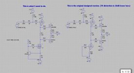
I took two pictures of the driver
- with IRF830 (first) & an active load (DN2540);
- and (second) with DN2540 & resistor.
The first one has an incredible risetime, but that exposes the output transformer resonance that is about 176 kHz. (Lundahl 1k8); there is even a bit of crosstalk of that resonance through the earth as you can see.
The second one has a slower response but the resonance is less present.
For that reason I retained the second one.
Driver = 5751 tube in parallel.
IRF830 & active load:

DN2540 & 43K:

The square wave is at about 7 KHz
(I must say in apology there are the slightest differences in ground connection between the two mono chassis)
- with IRF830 (first) & an active load (DN2540);
- and (second) with DN2540 & resistor.
The first one has an incredible risetime, but that exposes the output transformer resonance that is about 176 kHz. (Lundahl 1k8); there is even a bit of crosstalk of that resonance through the earth as you can see.
The second one has a slower response but the resonance is less present.
For that reason I retained the second one.
Driver = 5751 tube in parallel.
IRF830 & active load:
DN2540 & 43K:
The square wave is at about 7 KHz
(I must say in apology there are the slightest differences in ground connection between the two mono chassis)
Hi Guys, I did see this thread and I want ask something, mine hybrid amp, designed long ago and still playing, it do already for 13 years without failing I want to change the driver part to the mosfets, now I use two 6n6p one as cathode follower and one as a current source, do send a signal from the dc servo to the input of the cathode follower, that does work however was it a good idea? in mine case voltage is positive from the servo, but can go two sides when needed to get low offset, this is because the mosfets on output get drived in dc mode, so uge offset is present when tubes are cold, for this there is also a dc protection with longer wait time, and get in when offset is below treshold.
I want more play for tubes, and as such do remove the lower current source and replace by a mosfet, impedance is then higher also..
Because I saw your conversation about current sources I do put it here, I do not want to hyack you guys.
I want more play for tubes, and as such do remove the lower current source and replace by a mosfet, impedance is then higher also..
Because I saw your conversation about current sources I do put it here, I do not want to hyack you guys.
Attachments
Also, use a Vgs protection diode.
Yes I now, did forget to drawn.
Th DN2540 is very sensitive for gate overvoltage a transient is enough to kill it.
regards
I blew up a number of DN2540s before I started tacking a 15V zener from the gate to drain.
I have not blown one up since then.
Wait… Gate to Drain? Mmm… I think you mean to Source, for otherwise what is the point of using them with a 15 volt VGD?
⋅-⋅-⋅ Just saying, ⋅-⋅-⋅
⋅-=≡ GoatGuy ✓ ≡=-⋅
Question on DN2540: did anyone observe high gate current?
I wanted to make a buffer, loaded to V- with a constant current. Purpose: DC in and DC out, no caps.
I connected the gate of the DN2540 to earth with 120 K, and the gate current elevates the gate to + 5 volt.
I wanted to make a buffer, loaded to V- with a constant current. Purpose: DC in and DC out, no caps.
I connected the gate of the DN2540 to earth with 120 K, and the gate current elevates the gate to + 5 volt.
- Low resistance connected: it will work perfectly as CCS; increasing the Vb from 16 to 35V: no change in current.
- for instance by connecting a small J FET - think 2SK170 etc - directly on the pins. Then the gate goes to the GS of the JFET.
- Or with a resistor 39 ohms.
- The resistance source/drain is rather low, order of magnitude is 20-25 ohms. I bought mine from Farnell; I have a strip, and ones never used measure the same. .
If you have a drain-to-gate leakage of 42uA, that's beyond the specification for the 2540, and may just mean that you have some PCB or device surface leakage (example: solder flux).
But anyway, using high values of gate resistor is not a good idea, because the FET will break down at lower voltages than the datasheet value (the drain-gate leakage adds enhancement voltage, augmenting the avalanche current).
High Rg values can increase the risk of self-oscillation, too.
But anyway, using high values of gate resistor is not a good idea, because the FET will break down at lower voltages than the datasheet value (the drain-gate leakage adds enhancement voltage, augmenting the avalanche current).
High Rg values can increase the risk of self-oscillation, too.
Thanks, yes, I think you are right about the board: outside as a spiders nest it works, and once back on the board it goes awry . . . So solder flux? I have a LMP solder, gives off quite some goo; I habitually so not clean it …
And the specs say that even 1 mA leakage can be possible :
And the specs say that even 1 mA leakage can be possible :
I thought a Mosfet can stand high gate resiatnces, even like 1M. (in my test set I have 25V).1.0 mA @ VDS = 0.8 Max Rating, i.e 300V
 To sort things out I’ll take a fresh start . . .
- Home
- Amplifiers
- Tubes / Valves
- Source follower IRF720 or DN2540