Not to get off topic, you are certainly right. High gain sound is multiple gain stages stacked with tone controls inbetween, typically bass and treble cut, so the result signal is more like a squarewave than a sine, very compressed - and all that before the power stage. The particular amplifier has a power stage typical for guitar amps, cathode bias (like in VOX or Fender amplifiers). I always wondered why different tubes sound differently for guitar in the same amplifier. That would be for another thread, that I will start and I would very welcome your knowledge there. Edit: The thread is here: https://www.diyaudio.com/forums/ins...nd-amp-triode-pentode-switch.html#post6377402
To get slightly closer back to the original topic - in guitar amps, I always prefer 6L6 power tubes, but for HiFi, I was always happy with both EL34s and 6L6s and could most probably not tell them apart in a double blind test. Originally, I was a bit sceptical, but in the end, I am very happy with my A9 in multiamping setup, both for midrange and treble.
To get slightly closer back to the original topic - in guitar amps, I always prefer 6L6 power tubes, but for HiFi, I was always happy with both EL34s and 6L6s and could most probably not tell them apart in a double blind test. Originally, I was a bit sceptical, but in the end, I am very happy with my A9 in multiamping setup, both for midrange and treble.
Last edited:
Tubby23,
For an A9 amplifier (I think there are different parts and circuits depending on the
age/generation of that amp).
Amplifiers are made to a price point. They are not generally designed to be used at higher current levels, that would increase the cost of the power transformer.
But if I remember correctly, some of the owners were worried about the temperature of their power transformer, thinking it was a little high.
Running the amp at higher current may be more of a problem for the power transformer, than for the output tubes, but not all current production EL34 are as reliable as other current production EL34.
For the transformer, it may depend on the exact model of the power transformer, and the exact parts in the power supply.
More capacitance in the first cap immediately after the rectifier is a good example of more secondary heating, especially if the amp current draw is also higher.
I would expect that biasing the tube for more current might cause the actual maximum output power before clipping to go down (like if the driver signal was larger than the new lower grid to cathode (self) bias volts.
Another thing to consider is that the increased current will cause the output transformer to saturate at lower frequencies, even at reduced power levels.
It seems that I have seen several different schematics of these amplifiers; like different versions.
UL, Triode wired, Pentode, no negative feedback, negative feedback, SRPP input stage, parallel input triodes, etc.
Different output transformers, and different power transformers.
I can never follow which are original manufacturers multiple versions, or owners modified versions, etc.
Broad Sweeping Generalized statements about such amplifiers is just that, a Generalization.
Last edited:
Yes, mine is a modded A9.
However there's nothing special about the power stage apart from I having swapped out the OPTs for bigger 10W 3.5K and replacing the original cathode resistance of 500R (about 40% dissipation) with 270R (70% dissipation).
Regarding the power transformer, I replaced the original 5Z3P rectifier with a 5AR4 thus pulling 1A less in heater current.
Since I'm now saving 1A on the heater secondary do I now have that extra headroom to play around for more biasing?
Last edited:
1A less filament current, so 1A x 5V = 5 Watts saved.
But filaments are resistive, so there are no transient currents, the current is a sine wave.
Rectifiers that have a capacitor input filter, like the A9 have transient currents, not sine wave currents. Transient currents makes more heating of the B+ secondary windings, than a sine wave load would.
I do not remember the plate voltages and plate currents on the A9.
I will instead use an illustration.
500 Ohms and 50mA = 25V self bias
270 Ohms and 70mA = 19V self bias
Plate voltage 300V
300V - 25V = 275V
275V x 50 mA = 13.7 Watts plate dissipation
Plate voltage 300V
300V - 19V bias = 281V
281V x 70mA = 19.7 Watts plate dissipation
19.7W - 13.7W = 6 Watts increased power per EL34.
2 EL34 = 12 Watts more power in the tubes.
20mA x 2 = 40mA more B+ draw.
But there are voltage drops from the rectifier, choke, and output transformer DCR.
There is 140mA - 100mA = 50mA more draw from the B+
Suppose the voltage drop across the rectifier, choke, and output transformers DCRs is 50V.
That means we have 50V x 50mA more current draw = 2.5 Watts more power lost in the B+ and output transformer system.
We saved 5 Watts in the new rectifier filament.
But we used 12Watts more in the EL34 tubes.
And we used 2.5 Watts more in the B+ and Output transformer DCRs.
12W + 2.5W - 5W = 9.5 Watts more to power the amplifier.
Well, that is only part of the story . . .
The additional current draw causes more heating of both the primary windings and the B+ secondary windings of the power transformer; because of the increased current times the DCR voltage drops.
The smallest additional factor of power increase is the self bias resistors:
(0.05mA)squared x 500 Ohms = 1.25 Watts
(0.07mA)squared x 270 Ohms = 1.32 Watts
I think you can see, a simple small change of current to the EL34 tubes can cause a lot more heat into the output tubes, and into the power transformer.
You can not make up for that by changing the rectifier from a 3A to 2A filament.
158 degrees F is hotter than I run almost all of my power transformers.
Is that 63.5ma per plate, or per cathode (cathode current is plate + screen current).
And then you have 2x that for 2 output tubes.
I am not sure the A9 was ever designed for that much current).
Again, the designers of an inexpensive amplifier are only going to specify a power transformer that barely meets the needs of the amplifier's current draw.
Using a transformer that has lots of extra capability will make the amplifier more expensive to build, and when shipped across the ocean, more expensive to ship.
I don't know of an easy way to test a power transformer to determine its maximum safe operation.
When you purchase a transformer that is UL rated, you expect it to meet its specifications (rightly or wrongly, depending on the integrity of the manufacturer).
Just my opinions.
Last edited:
Best replacement tubes to the supplied EL34B?
Hi All,
My amp suddenly got the crackles. Checked everything out for any loose connections. Found quite a few especially on sockets. Repaired any found but still got the crackles. I now suspect one of the EL34's for which I have no replacements. Had replacements for all other tubes
As the title says what would be the best tubes to replace these power tubes on a budget ???
Can get Russian made KT77's to my budget locally but have read many bad reports about Russian tubes??
Last edited:
Crackling problem
The crackling is actually more prominent in the right channel. However, if I change the tubes right to left the crackling is still more evident in the right BUT it is also heard in the left channel to some extent.
This made me think the rectifier tube was at fault. However, on changing that tube nothing changes. Still crackles as before. I have some new tubes in the post and we will see if they fix the problem. I hope that they do and the problem is not more deep rooted.
Cheers.
Bobbie
Hi Tubby, Thanks for your reply.You have crackling on both channels?
If only one, try swapping the power tubes and then the drivers to find out which is/are bad.
The crackling is actually more prominent in the right channel. However, if I change the tubes right to left the crackling is still more evident in the right BUT it is also heard in the left channel to some extent.
This made me think the rectifier tube was at fault. However, on changing that tube nothing changes. Still crackles as before. I have some new tubes in the post and we will see if they fix the problem. I hope that they do and the problem is not more deep rooted.
Cheers.
Bobbie
Crackling Amp
Hi Tubby23 and all who suggested remedies,
Found the cause of the crackling. As I have mentioned previously I run the amp thru an el cheapo tone control pre-amp with input from from a bluetooth setup. The el cheapo tone control uses a 6k4 tube per channel and simply reseating these valves fixed the problem.
Thanks to all who had suggestions, much appreciated,
DIYBobbie
PS: Some may scoff at the use of this pre-amp. However, I can assure that it works well especially in the bass department
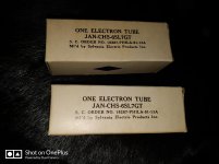
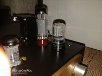
Just thought I'd share my latest upgrade.
I just swapped out my Tung-Sol SL7GT s for NOS Sylvania JAN-CHS-6SL7GT s and, oh my, what a difference they make!
The amp is noticeably brighter, with clearer treble and bass. The soundstage appears wider too.
Can't say if this will have the same effect on stock A9s - I added bypass caps and local negative feedback to my driver stage but I think it's worth a try - it certainly won't get any worst..
Attachments
Last edited:
- Home
- Amplifiers
- Tubes / Valves
- Boyuu EL34 A9 Tube Amp