Tubby23,
56% at 45.90mA.
90% (90/56) x 45.90 = 73.77mA
There will be the following changes in your amplifier:
The B+ Voltage will drop because of the additional load current.
The Power transformer will get hotter.
The Self Bias Voltage will go down (because you have to use less resistance than the 479 Ohms you are using now,
in order to get more current).
The B+ draw now is over 90mA.
It will be going to more than 147.5 mA.
How warm, or how hot does your power transformer get at the 45.9 mA/tube now?
How about the rectifier tube. Check the tube specifications for the new current (probably OK), But be sure to check the rectifier's rating of the capacitance of the first filter cap that is in your amp, versus the higher current level the rectifier will be running at.
Hello, it's very interesting what you're saying. Is there a way to simulate different values of resistors and voltage before modification.
It really involves many factors.
You need to know the DCR of the power transformer primary times the step up ratio, the DCR of the secondary of the power transformer, and the secondary voltage rating.
Then you need the rectifier curves to find its voltage drop at the load current (more if you use a cap input filter, less if you use choke loading).
Then you need to know the DCR of the choke and any other resistors in the B+ that are before the filter cap that runs the output stages.
Then, the current that you will run the output tubes at.
Then figure the B+, from all the voltage drops.
Cap input filters tend to be 1.414 times the secondary voltage (or 1/2 voltage if there is a center tap).
Choke input filters tend to be 0.9 times the secondary voltage (or 1/2 voltage if there is a center tap).
that is what the rectifier sees.
And, then all the drops in the DCRs x current, and the Rectifier drop at the load current.
Next, you need the curves of the output tubes.
You use the calculated B+, and reduce it by the output transformer primary DCR times the planned plate current.
Then, with the Plate voltage, and planned plate current, find the grid bias needed (or self bias needed) to get the planned plate current at that plate voltage (do not forget to re-calculate the plate to cathode voltage; the self bias voltage reduces it by the amount of the self bias).
The self bias voltage / the desired current = the self bias resistor.
Some people use the power supply software, and just enter the numbers.
I dislike software, so I wait until I have lots of energy, and calculate all this myself.
I cheat a little. I often use the same power transformer on many amplifiers, so I am familiar with the transformer.
And I use solid state rectifiers (no 15, 25, 50, or 60V tube rectifier drop, that varies versus tube type and current draw).
I use choke input filters when I can, given the power transformer, versus the B+ I need. Then I use a small capacitor before the choke input to adjust the B+ upward to get the exact voltage I need.
Last edited:
Tubby23,
56% at 45.90mA.
90% (90/56) x 45.90 = 73.77mA
There will be the following changes in your amplifier:
The B+ Voltage will drop because of the additional load current.
The Power transformer will get hotter.
The Self Bias Voltage will go down (because you have to use less resistance than the 479 Ohms you are using now,
in order to get more current).
The B+ draw now is over 90mA.
It will be going to more than 147.5 mA.
How warm, or how hot does your power transformer get at the 45.9 mA/tube now?
How about the rectifier tube. Check the tube specifications for the new current (probably OK), But be sure to check the rectifier's rating of the capacitance of the first filter cap that is in your amp, versus the higher current level the rectifier will be running at.
Hi.
My rectifier is the stock 5Z3P, in series with UF4007 diodes at the inputs.
My reservoir cap is a 22uf/450v, followed by a 330uf/450v after the choke and, lastly, one of the stock 33uf/400v "Phillips" after the 8.5k resistor.
I haven't any means of measuring the tranny's temperature but it, along with the whole amp, gets quite toasty.
Someone, I believe it was member "Learn", mentioned it's rated at 200w.
According to LtSpice B+ is currently drawing 91.92mA, measured at the choke.
Hello, it's very interesting what you're saying. Is there a way to simulate different values of resistors and voltage before modification.
Yes!
Attachments
It really involves many factors.
You need to know the DCR of the power transformer primary times the step up ratio, the DCR of the secondary of the power transformer, and the secondary voltage rating.
Then you need the rectifier curves to find its voltage drop at the load current (more if you use a cap input filter, less if you use choke loading).
Then you need to know the DCR of the choke and any other resistors in the B+ that are before the filter cap that runs the output stages.
Then, the current that you will run the output tubes at.
Then figure the B+, from all the voltage drops.
Cap input filters tend to be 1.414 times the secondary voltage (or 1/2 voltage if there is a center tap).
Choke input filters tend to be 0.9 times the secondary voltage (or 1/2 voltage if there is a center tap).
that is what the rectifier sees.
And, then all the drops in the DCRs x current, and the Rectifier drop at the load current.
Next, you need the curves of the output tubes.
You use the calculated B+, and reduce it by the output transformer primary DCR times the planned plate current.
Then, with the Plate voltage, and planned plate current, find the grid bias needed (or self bias needed) to get the planned plate current at that plate voltage (do not forget to re-calculate the plate to cathode voltage; the self bias voltage reduces it by the amount of the self bias).
The self bias voltage / the desired current = the self bias resistor.
Some people use the power supply software, and just enter the numbers.
I dislike software, so I wait until I have lots of energy, and calculate all this myself.
I cheat a little. I often use the same power transformer on many amplifiers, so I am familiar with the transformer.
And I use solid state rectifiers (no 15, 25, 50, or 60V tube rectifier drop, that varies versus tube type and current draw).
I use choke input filters when I can, given the power transformer, versus the B+ I need. Then I use a small capacitor before the choke input to adjust the B+ upward to get the exact voltage I need.
My OPTs primary DCRs are (L) 219R with 11v drop and (R) 222R also with 11v drop...hmmm..
My B+/HT is currently 332v and EL34 plates are both 321v
My 5Z3P stock rectifier is equivalent to 5U4G with the following specs:
(1550V PIV, 225mA max DC. 44V max drop at 225mA)
LTSpice won't model tube rectifiers but my virtual diode-based two-phase rectifier is outputting 445mA RMS at the moment...
But it shows that only 100mA are flowing through the choke..
I have no tranny spec data.
And that's all the info i can provide at the moment.
Last edited:
Tubby23,
I am not a software guy.
And I do not use Spice.
Try and model your 5Z3 as the following:
44V/225mA = 196 Ohms (I know, that tube resistance is dynamic not fixed, but for your spice model, use 196 Ohms in series with a HV diode).
Then, in spice, simulate the 5Z3 with the following model:
A high voltage rectifier diode in series with 196 Ohms.
You need two of those models to make it full wave, just like the 5Z3.
I think your mains are either 220 or 240V. The power transformer primaries are in series, right?
So, the DCR is 219 + 222 = 441 Ohms. You could never draw more than 1/2 Amp in 220V, even if the secondary was shorted.
I do not believe your DCR readings.
I think your DMM is reading the DCR improperly. You need to short the secondaries, then read the DCR again. DMMs get confused in the Ohmmeter mode, when measuring an inductor/transformer (but short the secondaries, and the primary inductance "goes away").
Likewise,
When you measure the secondary DCR, then remember to short both the primary windings. That will help your DMM Ohmmeter to get the right reading.
If the 1/2 winding of the secondary is 332V rms, then the correct DCR multiplier for the primary is:
whole primary DCR x 332/220, or 332/240. 1.51, or 1.38 Get it?
And be sure to measure across 1/2 of the secondary, I am not sure if it is 332VAC.
Do not confuse B+ VDC with /12 primary VAC.
I do not believe your Boyuu A9 is putting out 445mA RMS.
Where did you get that?
Your mains are 50Hz, right. So full wave rectification is 100Hz.
At 100 Hz, 22uF has 72 Ohms of capacitive reactance.
You have a 33 Ohm resistor in series with that.
When the amp is first turned on, the rectifier sees a very large transient current, and then sees 33 Ohms in series with 72 Ohms to ground = 105 Ohms.
The DCRs of the primary (times the correct multiplier), and the DCR of the 1/2 secondary winding are also in series with the 105 Ohms.
That dictates the transient current, and it might just be 445mA, but not 445mARMS.
And, after the B+ capacitors charge up, the current is far less.
Last edited:
6A3sUMMER
Those DCR measurements were of my output transformers, not the power unit. I haven't ever taken any measurements of it.
I have it modelled in spice as an ideal transformer.
Yes, UK mains is officially 230v but mine fluctuates from 232-238v, depending on local loading, whatever factors.
Just two days ago I was taking the power stage's measurements and B+ would go up and down by 2v every so often, affecting the other voltages.
Currently, I have the rectifier modelled as an ideal full wave diode-based unit. I get similar rail voltages in the software as those of my amplifier simply by fudging the mains voltage up or down a few volts (which actually reflects my local mains, lol).
But I'll try your suggestion of additional resistors in series with the diodes. Question: the rectifier tube's 44v drop isn't purely resistive but what else is it? Reactive? Inductive? I ask because instead of resistors maybe I could put coils or caps instead, or a combination.
With regards to your valid concerns over the A9's power dissipation, once I increase the biasing, I only want to increase it enough for the bigger 15w/6.6Z OPTs I'm going to order. And bandwidth
The Boyuu A9 is offered in a version with bigger OPTs already installed but I haven't any specs for those but I'm guessing 12w more or less.
Thank you for your interest.
I fixed up an old Knight integrated that runs cathode biased el34s at max dissipation. Once I cleared out the weird high impedance pads in the stock circuit, I was pleasantly surprised by how it sounded.
What was about the sound that seemed better?
All the guitar guys rave about it being brighter, less flat, etc.
Was wondering what the hi-fi guys have to say about that.
Increasing the bias current (whithin reason) increases the tube's linearity but decreases the OPT linearity, especially in the LF region, so there's an optimum somewhere.
Unfortunately, it is impossible to tell where it is exactly without having the full data on the OPT, so the only way to find it in this case is to experiment.
Unfortunately, it is impossible to tell where it is exactly without having the full data on the OPT, so the only way to find it in this case is to experiment.
Increasing the bias current (whithin reason) increases the tube's linearity but decreases the OPT linearity, especially in the LF region, so there's an optimum somewhere.
Unfortunately, it is impossible to tell where it is exactly without having the full data on the OPT, so the only way to find it in this case is to experiment.
Have you tried it yourself on this amp, TG?
I've imputed the default/stock numbers into this calculator:
Universal loadline calculator for vacuum tubes - Vacuum Tube Amplifiers - DIY
and it seems like the performance envelope of the EL34 is being wasted.
No, I haven't since I don't own one and I generally avoid buying kits with unknown part for those very reasons.
Yes, EL34s look heavily underbiased in this case. But still we don't know what these PT and OPTs are capable of.
I would suggest gradually increasing the bias current (like 5-10mA at a time) while measuring the amp THD performance at, say, 40Hz at full power (you'll need the dummy load) and measuring the PT temperature (there is an exposed part of the bobbin underneath the chassis - you should definitely stop at about 35°C).
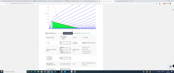
So, with my current cathode resistor of 497R (500R) the readings are:
Plate-to-Cathode: 297v
Total plate current: 44.1mA
Plate dissipation: 13.1w / 52% of max
I plugged these figures into this website:
Universal loadline calculator for vacuum tubes - Vacuum Tube Amplifiers - DIY
And obtained the first graph:
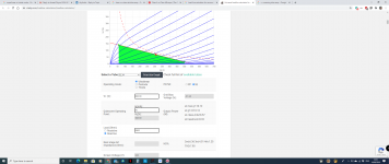
But if I replaced the 497R cathode resistor with a 270R I'd get:
Plate-to-Cathode: 308.39v
Total plate current: 70mA
Plate dissipation: 21.6w / 86% of max
Hence the second graph
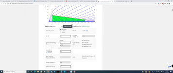
The third is with both a 270R Kr and OPT with 6.6K impedance.
Spice seems to show the voltage swing to be around +-250v.
The 270R resistor allows the swing to be taken into higher volumes (headroom).
Anyone care to check these figures, please?
They're potentially good for all of us!
Plate-to-Cathode: 297v
Total plate current: 44.1mA
Plate dissipation: 13.1w / 52% of max
I plugged these figures into this website:
Universal loadline calculator for vacuum tubes - Vacuum Tube Amplifiers - DIY
And obtained the first graph:
But if I replaced the 497R cathode resistor with a 270R I'd get:
Plate-to-Cathode: 308.39v
Total plate current: 70mA
Plate dissipation: 21.6w / 86% of max
Hence the second graph
The third is with both a 270R Kr and OPT with 6.6K impedance.
Spice seems to show the voltage swing to be around +-250v.
The 270R resistor allows the swing to be taken into higher volumes (headroom).
Anyone care to check these figures, please?
They're potentially good for all of us!
Attachments
Tubby23,
There will be the following changes in your amplifier:
The B+ Voltage will drop because of the additional load current.
The Power transformer will get hotter.
The Self Bias Voltage will go down (because you have to use less resistance than the 479 Ohms you are using now,
in order to get more current).
The B+ would sag but so would the voltage drop across everything else, including the cathode resistor, so the plate-to-cathode voltage would remain the same?
Edit: And would it sag or just pull more power from the mains?
Last edited:
No, I haven't since I don't own one and I generally avoid buying kits with unknown part for those very reasons.
Yes, EL34s look heavily underbiased in this case. But still we don't know what these PT and OPTs are capable of.
I would suggest gradually increasing the bias current (like 5-10mA at a time) while measuring the amp THD performance at, say, 40Hz at full power (you'll need the dummy load) and measuring the PT temperature (there is an exposed part of the bobbin underneath the chassis - you should definitely stop at about 35°C).
Can i guesstimate the THD simply by looking at prefectly formed (or not) 40Hz sinewaves on my oscilloscope?
Also, how can i measure the exposed bobin's temp? The whole amp gets quite warm. Maybe if i had one of those spot meter thingys..
Tubby23,
If B+ sags, that means you are drawing more current (which is what happens when you reduce the resistance of the cathode self bias resistor).
The additional current requirement will cause an additional current on the power transformer primary.
The mains power voltage will remain relatively constant (if not, you need to replace your house wiring).
More current times the same mains voltage = more power, more heating of the power transformer.
No free lunch here.
The output transformer will have more DC current in it.
At 40Hz, it will saturate earlier (at a Lower power).
An output transformer in saturation causes distortion.
I can"see" the wave shape on the scope in my minds eye (seen it before).
Tradeoffs will happen.
Last edited:
Tubby23,
If B+ sags, that means you are drawing more current (which is what happens when you reduce the resistance of the cathode self bias resistor).
The additional current requirement will cause an additional current on the power transformer primary.
The mains power voltage will remain relatively constant (if not, you need to replace your house wiring).
More current times the same mains voltage = more power, more heating of the power transformer.
No free lunch here.
The output transformer will have more DC current in it.
At 40Hz, it will saturate earlier (at a Lower power).
An output transformer in saturation causes distortion.
I can"see" the wave shape on the scope in my minds eye (seen it before).
Tradeoffs will happen.
I've seen the wave too on my scope with my current set-up (stock bias).
Starts at around 30hz. At 20hz it looks like you can surf it!
My EV charging may have something to do with my household voltage sagging - 16 amps when first connected.
Someone in this thread apparently runs KT88s instead of EL34s and claims the transformer to handle 200w. It is a chunky transformer, TBH I'd be surprised if it couldn't handle an extra 40-50mA.
I've asked this before, but I'm thick so i'm asking again:
If I'm plotting a loadline on a blank datasheet for a cathode-biased, reactive load, such as my power stage, what V do I use?
Is it V=HT, B+, etc ?
or V=HT-(Voltage drop from xfmr DCR primary)=Va (anode)
or V=Va-Vk (cathode voltage drop) ?
There's lots of guides on how to plot loadlines but they're all for fixed bias set-ups and V seems to be equal to HT, B+, etc.
Well, by the moment you can see the distortion on the oscilloscope, the THD is already about 2-3%.
And decent DMMs with thermal probe are like £10 nowadays.
Didn't know these were a thing - and affordable too.
I'll take a look.
But if I replaced the 497R cathode resistor with a 270R I'd get:
Plate-to-Cathode: 308.39v
Total plate current: 70mA
Plate dissipation: 21.6w / 86% of max
I tested this more than a year ago with different cathode resistors, at that time I was thinking it would be nice to get 90% of max dissipation.
Cathode resistor R ----- % of max dissipation
277R -------- 72-75%
340R -------- 70.7%
410R -------- 67.4%
430R -------- 66.5%
469R -------- 64.5%
478R -------- 62%
To be honest, I could not hear the warmer sound by increasing the dissipation, there was difference only because the overall output power increased, this can be easily mistaken as warmth of sound.
I compared with my new push and pull tube amp (Cayin). the A9 is just doing fine, being biased at 60% of max dissipation.
PS: it seems the power supply transformer is OK. at 62% the overall wattage of the device was 86 watt and, at 75% was 101 watt. I pushed the device to work with KT88, that is 120watt of total power consumption, the transformer was just warm after hours of playing
- Home
- Amplifiers
- Tubes / Valves
- Boyuu EL34 A9 Tube Amp