Here are some pics.
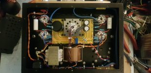
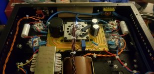
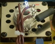
I connected the speaker 0 output terminals together and took the common together with the schematic (pcb) 0V and screwed them to the chassis along with the earth wire from the mains inlet. I used the choke mounting point next to the circuit board as an anchor. Along with the input tube heater wiring mod, this arrangement gives a satisfactory noise performance
I connected the speaker 0 output terminals together and took the common together with the schematic (pcb) 0V and screwed them to the chassis along with the earth wire from the mains inlet. I used the choke mounting point next to the circuit board as an anchor. Along with the input tube heater wiring mod, this arrangement gives a satisfactory noise performance
Attachments
Hi Giulio, I built one of these amps recently, it is very quiet even through very efficient loudspeakers.
Very clean job on the wiring - nice! I'm assuming when you say it is 'very quiet' that it has very low hum but is loud enough when playing music!
")
Sometimes people report amps being 'very quiet' when they don't produce enough power... Experimenting with using different points on the circuit ground/earth/0V for the single chassis ground connection can help to find the best place to make that connection, if hum is still a problem. (Ex: at the power supply filter, at the input, etc.)
Last edited:
I'm assuming when you say it is 'very quiet' that it has very low hum but is loud enough when playing music!
Hello Victoriaguy, thanks for the compliment.
Yes, it is delivering decent power with very low hum levels. I am very happy with its performance. Amazing value for the money.
Hi, thank you all for the useful advice.
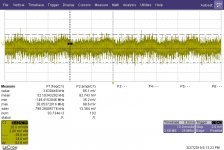
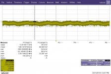
I attach a couple of pics taken with the scope, showing the output of one channel (they both behave the same). The output of the amp was connected to a dummy 4 ohm resistor. The voltage across the resistor was then measured with a LeCroy scope, using a 1MOhm passive probe in AC. With no audio input (input shorted), at minimum volume the pk2pk noise at the output is around 23 mV. If at all, residual 50Hz is seen but it is completely inaudible through the speaker. At maximum volume, still with no audio input, the pk2pk noise is around 60mV. This is already audible through the speaker, although it is not loud at all. Its first harmonic seems around 100Hz, as you can deduce from the 10 ms timebase, maybe it is coming from the rectifier. Not a big issue really, I am very satisfied with this amp!
Also I left the ground of the circuit floating with respect to the chassis, which is connected to earth. I will try to connect them together as Kris suggests.
Attachments
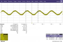
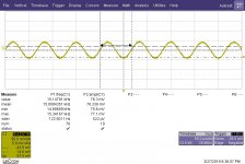
Another interesting piece of information. I tried to drive the input of the amp with a function generator, providing a sine wave 100mV pk2pk amplitude. The low cutoff frequency seems to be around 25Hz, the high is above 15kHz, as you can see from the amplitude (of C1). The waves look clean but ideally I should FFT them to investigate better the amp distortion.
Attachments
please tell me what are the white caps, the blue unit on the board any other change of parts you have made.
Hi Max, thanks for the compliment.
All the changes I made were gleaned from the several hours of reading this thread.
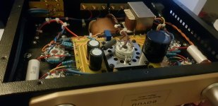
The white capacitors are 0.47uF 630V polyester types, I just happened to have them in my parts bin but Vishay or Cornell Dubilier make equivalent components. I wanted to use axial capacitors in the point to point positions. I used Elna 220uF 63V axial types to bypass the cathode resistors.
On the power supply board I replaced the two 22uF 450V caps, C301 and C303, with 33uF 500V types and C302 220uF 400V with a 330uF 450V low profile electrolytic which at 35mm high just manages to fit into the amp when mounted as seen. It is an Epcos product but there is a Rubycon type which is even shorter, at 30mm high, available from Mouser. I used higher voltage rated caps as the no-load voltage climbs to 448V at start up. The blue cap is a 0.1uF 630V polyester. It is in parallel with C302 and it's probably not necessary. it just happened to fit the space on the board!
To finish, I used some Van Damme screened cable for the input wiring.
All in all, it took me around 10 hours of work at a leisurely pace over a week or so and I must say, I highly enjoyed putting it together.
I hope you have as much fun as I did.
Thanks again to the Forum family.
I am new to here,first post, hope it worksYou do know that the tube pins are numbered clockwise, looking at the bottom of the tube? -i.e. from the inside of the chassis-
Thanks for all the information and thanks to the long weekend I had the chance to read through all the posts. I have ordered my A9 kit(I suppose, unlikely to be A10) from Ebay. It probably will take another week to arrive. So now I just got myself familiarise all the information and mistakes to avoid. I only have one question (after reading 900+) posts! It still might be a stupid one. Anyway, I found a few pictures , including the above Kris Rocka's picture. Regarding the transformer cables wiring on the power tube 5z3p. I can tell where the pin 8 is , by identify the R301 the only resistor there. Then it appears to me the filament power cable, if it's in the same pair, the other end was connected to pin 6,instead of pin 2. I understand our diyers already successfully finished the amplified, It could not be a mistake, Did I count the pins wrong ?
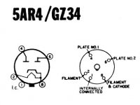
Hello Daniellu, The 5 Volt filament winding is connected to pins 2 and 8. R301 is connected to pin 2, look carefully at the supplier's stock photo and you will see it a bit more clearly.
Pins 4 and 6 are connected to the high voltage winding. I have attached the suppliers photo for comparison.
Note that you can connect R301 to either pin 2 or 8. The circuit diagram shows R301 connected to pin 8, but it is more convenient to use pin 2.
I hope it helps.
Pins 4 and 6 are connected to the high voltage winding. I have attached the suppliers photo for comparison.
Note that you can connect R301 to either pin 2 or 8. The circuit diagram shows R301 connected to pin 8, but it is more convenient to use pin 2.
I hope it helps.
Attachments

I hope it helps.

Attachments
Thanks Kris and VictoriaGuy!
Now it totally makes sense to me(Boyuu 's A9 diagram,R301 always connected to Pin8, but they supply the picture ,connected to pin2) . I did research a few pictures here and online elsewhere, The R301 was connected either pin 2 or 8. I looked the schematics now, yes the pin 2 , 8 and the transformer output coil are in the same closed loop,symmetrical and interchangeable . That makes pin 2 and 8 'same ' in outputting to R301. Thank you both very much, happy Easter.
Daniel
Last edited:
Any builder of that amp, should check to see if the specific rectifier that is installed is an Indirectly heated model (has a real cathode, not just a filament).
The indirectly heated cathode connection is usually on pin 8.
For an indirectly heated rectifier, if you connect R301 to pin 2, that would make the cathode current have to travel through the filament.
For example, 2 amps of the 5V filament winding through the filament, plus another 1/2 amp of peak cathode current all going through the 5V filament on its way to R301 and the B+ filter.
Therefore, the correct connection of R301 would be to pin 8.
Thank you for explain this! I definitely will connect the resistor to Pin 8. It puzzled me before I was so worried their amplifier in big trouble if connected incorrectlyTherefore, the correct connection of R301 would be to pin 8.
Any builder of that amp, should check to see if the specific rectifier that is installed is an Indirectly heated model (has a real cathode, not just a filament).
The indirectly heated cathode connection is usually on pin 8.
It's always a possibility that 'down the road' some future owner will decide to use a different rectifier tube (tube rolling knows no limits!), so the pin 8 recommendation is a good one to follow, even if a directly heated rectifier tube is specified/installed.
Attachments
Any builder of that amp, should check to see if the specific rectifier that is installed is an Indirectly heated model (has a real cathode, not just a filament).
Hmmm... It seems that 5Z4P is indeed a (half!?) directly heated rectifier but I am now conflicted as there are 5Z4 tubes pin-out diagrams which are showing indirectly heated cathodes. This will probably not make much difference to the B+ as the filament impedance is around 2.5 Ohms. I think this might have been mentioned earlier in this or another thread on the A9.
However, thanks to 6A3sUmmer I will be getting my de-soldering station out very shortly!
Last edited:
- Home
- Amplifiers
- Tubes / Valves
- Boyuu EL34 A9 Tube Amp