The only reason to put that cap between the volume control and R102 is to keep DC from the signal source getting to the grid. It is easy to test if any of your signal sources have any DC at their output. Just read it with a DMM set to DC mode. If there is very much DC from the signal source, it may be that the signal source needs to be fixed.
Agreed,
Many electrolytics can have some DC leakage (defeats the purpose of getting rid of the DC). Electrolytics have much much more leakage than a plastic film cap.
Agreed, you do not need 4.7uF.
How many of you need frequency response that is -3 dB at 0.45 Hz (less than 1/2 Hz). (4.7uF and 150k Ohms) What recording of what musical instrument has that frequency?
I'd put it in the spot that's easier, choosing between those two. If both choices were equally convenient, I'd put it 'before' the potentiometer to keep DC (if any) off the pot.Thank you VictoriaGuy.
Where is the best place to put this capacitor, where is showing in the diagram or at the input before the potentiometer?
Cheers
As 6A3 said, there shouldn't be DC from your sources, but having the cap there is easy so I'd add it.
BTW - a disclaimer: Years ago I built a 'cap switching gizmo' to do some listening tests and I proved to myself that I can't hear any difference between 'ordinary' and 'audiophile' caps. Some folks 'can', so for them, adding any caps to the 'signal path' is undesirable.
Thank you guys.
BTW, I've measured and my source does not have any DC so I'm NOT adding that capacitor.
I've picked the 4.7uF value for the capacitor because that's a common value I've seen for audio decoupling capacitors in transistors amps but, thanks to you guys, I'm learning that tube amps are different calculations than transistors amp.
Thanks again.
Gents,
Again, I'm learning a lot about tube amps with this group and I really appreciate all your answers and technical explanations you guys are giving me. You guys are great!!
I would like to pick your brain one more time. This is specific to my amp but I think it would be a good knowledge to all in this forum.
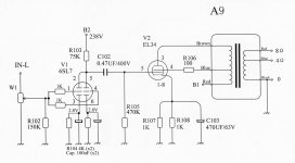
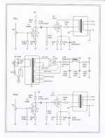
Please take a look again at the diagram of my A9 amp (attached).
I've been reading about how to correctly calculate bias in a triode tube and I learn the following:
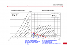
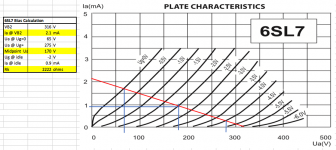
Choose a voltage to power the tube (in my case is 238V) Choose a resistor to tube anode (in my case R103 is 75K. but each plate sees as a 150K resistor) Calculate the currents assuming tube is in short (max) and tube is in open (min): ip= 238V/150K -> Ip= 1.6mA for max and Ip = 0 for min. Plot these values on the tube Plate Characteristics graphic. Mine is for 6SL7 (see picture) Then on graphic you pick the point where the Ip line crosses grid voltage Ug @ 0 volts and @ Ug is still linear. (in my case I picked Ug -3V) Then you read the Ua voltages and pick the voltage in the middle. Let's call this "Ua idle". (In my case Ua1= 35V, Ua2 = 200V and mid point is 118V) From there you see where the Ua idle line crosses the Ip current line and that will be your Ug for idle. in my case was -1.5V Then you read in graphic the Ip current for idle. (in my case was approximately 0.6mA. With the this Ug and Ip you calculate the value of the cathode resistor for Vk. in my case Rk=Ug/Ip -> Rk= 1.5V/0.6mA, Rk= 2.5K)
So if all the above is correct, my 6SL7 tube should have 2.5K cathode resistors which would put the cathode voltages at about 1.5V. But in my amp I currently have Rk 4K and the cathode voltage is 2.8V, which makes Ug -2.8V. And if you look where Ug -2.8V is in the curve, it is really in a bad point of the curve.
I would like your comments in: 1) If the above method to calculate bias is correct. 2) If I should change my cathode resistors to have Ug at -1.5V.
Thanks
Again, I'm learning a lot about tube amps with this group and I really appreciate all your answers and technical explanations you guys are giving me. You guys are great!!
I would like to pick your brain one more time. This is specific to my amp but I think it would be a good knowledge to all in this forum.
Please take a look again at the diagram of my A9 amp (attached).
I've been reading about how to correctly calculate bias in a triode tube and I learn the following:
Choose a voltage to power the tube (in my case is 238V) Choose a resistor to tube anode (in my case R103 is 75K. but each plate sees as a 150K resistor) Calculate the currents assuming tube is in short (max) and tube is in open (min): ip= 238V/150K -> Ip= 1.6mA for max and Ip = 0 for min. Plot these values on the tube Plate Characteristics graphic. Mine is for 6SL7 (see picture) Then on graphic you pick the point where the Ip line crosses grid voltage Ug @ 0 volts and @ Ug is still linear. (in my case I picked Ug -3V) Then you read the Ua voltages and pick the voltage in the middle. Let's call this "Ua idle". (In my case Ua1= 35V, Ua2 = 200V and mid point is 118V) From there you see where the Ua idle line crosses the Ip current line and that will be your Ug for idle. in my case was -1.5V Then you read in graphic the Ip current for idle. (in my case was approximately 0.6mA. With the this Ug and Ip you calculate the value of the cathode resistor for Vk. in my case Rk=Ug/Ip -> Rk= 1.5V/0.6mA, Rk= 2.5K)
So if all the above is correct, my 6SL7 tube should have 2.5K cathode resistors which would put the cathode voltages at about 1.5V. But in my amp I currently have Rk 4K and the cathode voltage is 2.8V, which makes Ug -2.8V. And if you look where Ug -2.8V is in the curve, it is really in a bad point of the curve.
I would like your comments in: 1) If the above method to calculate bias is correct. 2) If I should change my cathode resistors to have Ug at -1.5V.
Thanks
Attachments
Fdlima,
Before I try and answer about what the driver should be like . . .
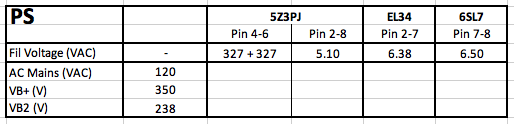
Can you tell me what is the DC voltage on the EL34 Cathodes, Left and Right channels?
Also, this thread has many schematics, started out as SRPP 6N9P, went to common cathode parallel triode 6N9PJ, and perhaps others, and now is 6SL7.
These tubes may be somewhat equivalent, or may not be for all circuits.
Before I try and answer about what the driver should be like . . .
Can you tell me what is the DC voltage on the EL34 Cathodes, Left and Right channels?
Also, this thread has many schematics, started out as SRPP 6N9P, went to common cathode parallel triode 6N9PJ, and perhaps others, and now is 6SL7.
These tubes may be somewhat equivalent, or may not be for all circuits.
Hi 6A3,
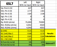
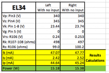
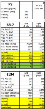
Here are all measurements from my amp. The cells in yellow and green are calculated results.
BTW, I don't think I can upload Excel files to this forum. correct?
Thanks,
Frank
Here are all measurements from my amp. The cells in yellow and green are calculated results.
BTW, I don't think I can upload Excel files to this forum. correct?
Thanks,
Frank
Attachments
Fdlima,
The EL34 Cathode voltage is (almost) 25V.
The EL34 grid is at 0 Volts.
The EL34 grid to cathode is -25V (the grid is more negative than the cathode by 25V).
The 6SL7 plates are at +227V.
The 6SL7 plates have to be capable of swinging +25V to - 25V above and below +227V (+252V to + 202V), in order to fully drive the EL34 grid.
(the coupling cap makes the EL34 grid voltage go from +25V to -25V).
The EL34 grid to cathode is -25V
-25V grid to cathode + 25V from the driver plate coupling cap = 0V grid to cathode.
-25V grid to cathode - 25V from the driver plate coupling cap = -50V grid to cathode.
You start with what the EL34 tube needs at the grid (in this case +/-25V),
Then you design a driver that has enough gain (according to your signal source voltage swing), and that can swing the +/-25V. That will drive the EL34 to clipping. Just a little lower signal from the volume control is the loudest you will listen to.
Fdlima,
My post # 888 is quite distorted from the 35/30 = 17%. That was a very first cut. But a different resistor, etc. might give a better result.
The one with 75k is 83/82 = only 1.2%, but watch for two things:
1. With no distortion in the driver, the 2nd harmonic distortion in the EL34 does not get cancelled (you might like it that way).
2. With the operation so far down on the 6SL7 curves, you will likely get a very wide
range of distortion from one tube to another (or even from one triode to the other triode in the same tube).
Hi 6A3,
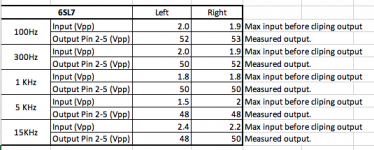
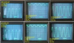
I have also done some measurements on the output (plate) of the 6SL7 tube (using the oscilloscope) and the results are in the table in this picture.
The way I did was I had one channels of the oscilloscope connected to the output of the 6SL7 tube (pins 2-5) and the other channels connected to input of the amp (on center tap of the potentiometer)
Then I started increasing the input signal until start seeing some distortion in the output signal.
Then I lowered the input signal slighty to the point just before seeing distortion in the output signal.
I then measured the input signal and the output signal and those are the maximum values before clipping.
As you can see in the table, for some frequencies, I'm not getting the 50Vpp (+/- 25V) swing, before clipping, that I need to drive the EL34. So I guess I should change the resistor value to get a better results?
Cheers,
Frank
Attachments
Your peak to peak measurement does not tell us anything about the symmetry or the non-symmetry of the output signal. non-symmetry is primarily 2nd Harmonic distortion.
A re-design would require changing the plate load resistor, self bias resistor, quiescent current, and quiescent plate voltage.
By the curves and values you showed on your tube curves, post # 885, you will likely not get lower distortion, but you do need to test and verify that it is actually the 1.2% that the curves showed.
You will need to separately measure the Peak +, Min -, and compare them (un-equal is 2nd harmonic distortion).
Since the plate is at a + voltage, you should measure by using AC coupling in the scope. If you do not have AC coupling that can handle +290V, then measure the EL34 Grid peak and min. Reference to 0V, the Peak +, and Min - are the real excursions.
Remember, when the grid goes more positive than the cathode, it will draw grid current, drive the average cathode voltage up, and the grid current will also distort the driver signal.
Clipping at both the peak + and min - is 3rd harmonic distortion.
If you have an FFT in your scope, you can measure the 2nd and 3rd harmonics.
Did you attach pictures to Post # 888?Fdlima,
My post # 888 is quite distorted from the 35/30 = 17%.
I can't see them.
VictoriaGuy,
In post 888 some of my edits were lost in hyperspace.
Fdlima was having trouble getting +/- 25V swing to drive the EL34, which has about 24 or 25V bias.
I did a first cut try with a different operating point on the 6SL7. The new operating point could easily do +/- 25V, but it was unsymmetrical, at +30V and - 35V, with +/- 1V input. That unsymmetrical gain is 2nd Harmonic distortion. To get +/-25V at low 2nd Harmonic distortion will require a re-design of the 6SL7 operating point, and cathode and plate resistors.
I am sorry for the confusion.
Thanks!I am sorry for the confusion.
I'm easily confused at the best of times; I just assumed I was having a bad evening!

This problem with getting enough swing at the EL34s may be why I was advised to re-wire my similar EL34 kit with a 'series' triode arrangement (SRPP? Totem Pole?). I didn't understand why, but just took the advice from my betters and built it and it sounds just fine....to me.
Hi,
I modified my amp this weekend and I replaced the 4K cathode resistors (6SL7) with 2K resistors and now I have a nice swing on the output of 6SL7 of 145V to 195V (50Vpp). The voltages seen better too.
The input can go up to 1.1Vpp before the output of 6SL7 starts loosing symmetry or having signs of the 2nd Harmonic. the output is about 50Vpp.
But although the 6SL7 can output up to 50Vpp, the input of the EL34 can only take up to 35Vpp before the output starts having distortions. For 35Vpp at the input of EL34, the output is about 165Vpp. Sorry I did not take pictures of the signal at output of EL34.
As always, your comments are very welcome.
Cheers
Attachments
Fdlima,
1. Some calculations and assumptions:
35V peak to peak = 17.5V peak
165V peak to peak = 82.5V peak
EL34 u = 11
82.5V / 17.5V = EL34 Gain = ~ 4.7
That is about 1/2 x u
It sounds like the EL34 is triode wired.
What is the transformer primary impedance? Suppose it is 2,500 Ohms, then . . .
P = ((V peak) squared) / (R x 2)
P = (82.5V peak squared) / (2500 x 2)
P = 1.36 Watts rms
2. Testing the output of the amp, with an 8 Ohm load on the 8 Ohm tap:
root (P x R) = Vrms
With P = 1.36W and R = 8 Ohms, V = 3.3 Vrms
Vrms x 2.828 = V peak to peak
3.3Vrms x 2.828 = 9.33V peak to peak
Is 9.33V peak to peak about what you get, with 165V peak to peak on the EL34 Plate?
Thank you 6A3,
What do you mean by "It sounds like the EL34 is triode wired"? Does it mean defective?
I will be traveling on on vacation until march 1st so I won't be working on my amp until then. I will check the transformer primary impedance when I come back from vacation.
For now my amp will be sitting at my men cave.
Cheers,
Frank
Attachments
Fdlima,
I did not mean the "sound of" triode wired.
But I did mean "it seems" the lower power out you are getting could be triode wired.
Otherwise, we have to find out why the power is low.
Of course I do not know the actual power you got, because I do not know what primary load impedance your transformer has. I need to know that to calculate the power result from the impedance and 165V peak to peak swing.
There is also some power loss due to the output transformer, perhaps 1 dB.
For example, if you had 2 Watts at the primary, and 1dB loss, you would get 1.6 Watts at the output tap.
I think the 'stock' schematic shows UL connection with a screen stopper?Fdlima,
I did not mean the "sound of" triode wired.
But I did mean "it seems" the lower power out you are getting could be triode wired.
Otherwise, we have to find out why the power is low.
Attachments
- Home
- Amplifiers
- Tubes / Valves
- Boyuu EL34 A9 Tube Amp