Measure the distance between the grill holes protect the lamps.Thank you - I think that is for the A10 amp. Mine is the A9 which I believe is a different size? Will look at the site to see if they have an A9 version....
Boyuu a10 250mm x 70mm
These amps are like brothers, maybe this part will suit you.
LongRoad,
The switched inputs to the voltage divider is a good idea. I do get the idea, and I do not drink alcohol.
But, you may not want to overdo it (depends on what CDs you listen to). So much music on CDs today is highly compressed to have output at or near max. They will output 2.5V on your CD player output.
However, some CDs maximum output is about 10dB lower than full scale DAC out. This makes it easy for CD players that do not have good IC amplifiers in the output stage. -10dB is 1/10 of the power. P = ((E)squared)/R -10dB is 1/((Root(10)) of full output voltage. (1/3.16) 2.5V x 1/3.16 = 0.790V Those low level CDs will not play at full power/volume with the CD input divider you have.
Got another quick question. Am considering buying a pair of uber-efficient Klipsch speakers for my Boyuu A9 from a fellow I know. I have a choice of Heresy 1 or 2 or KG4 speakers - he is a Klipsch collector. I am most familiar with the Heresy 1 as I used to sell the full klipsch lineup in the military PX system overseas from 1982 - 1984. The KG4 did not come out until 85 and has a passive radiator on the back. I will be auditioning but pretty sure the KG4 strengths are in the bottom end while Heresy are known to be lacking down low. The trade-off is the 3-way Heresy's have a better mid-range while the 2-way KG4 I hear lacks in that department - that is not my issue though. The Boyuu has terminals for 8 Ohm and 4 Ohm speakers. Heresy are 8 Ohm while the KG4 is 6 OHM. If I do like the KG4 then what terminals should I plug into - the 8 or 4 Ohm only? Can I add a resistor to either to make one a 6 ohm terminal or is that ill-advised hence locking me into the Heresy 1's or 2's?
Hi navydiver,
No need. Try either and use the one that sounds the best. All speakers have a lot of variance in their impedance as the frequency is swept. So a 6R speaker could be closer to either a 4R or 8R. It will not harm your amplifier, so don't worry about getting the exact impedance.
I recently bought a pair of Klipsch speakers, the RP-280F. Pretty good speakers, and efficient.
-Chris
Thank you muchly Anatech - I had pretty much thought that as I am familiar with the fact that speaker impedance changes quite dramatically wrt freq and load. I just wasn't quite sure wrt the tube amp since unlike solid state amps, tube amps seem to have tailored impedance outputs so wasn't sure what kind of tolerances were involved. I am actually leaning towards the KG4 on paper (and price) but will see what my "Mark 1" ears dictate tomorrow up close and personal...")
Cheers
Tim
Cheers
Tim
The switched inputs to the voltage divider is a good idea. I do get the idea, and I do not drink alcohol. <snip>
Pro beer was a joke, I hope you will appreciate

That's why I left the second input (aux) for devices with a standard signal level.
Last edited:
Hi,
I have to say this forum is excellent and helped me a lot in getting my A9 amp finished. The information contained here is a must since the kit doesn't comes with instructions. I have been reading the posts for about 4 while waiting for my kit to arrive to prepared for the job.
I finished my amp yesterday, triple checked the wiring and tuned it on. No fires but I only a loud hum on both channels. I when back to post and learned that pin 4 of the 6N9P needs to be connected to pin 1 (post from Ygg-it on page 4. Thank you @ygg-it). I connected the pins and I got the amp working but with a hum. My and kit came with a schematic diagram but, 4 years after that post, still showed pin 4 not connected to anything. I can't believe they have not yet corrected the diagram.
I fixed the hum with a suggestion from Gido on page 12 (Thank you @gido) and now the amp is working fine.
My kit came with with 4 resistor that are different from most diagrams I've seen in this post:
R103/R203: Mine is 100K (75K in other diagrams posted)
R105/R205: Mine is 330K (470K in other diagrams posted)
Does anybody know if these different resistor are because they have improved the sound or performance of the kit or is this just an error as we've seen before?
What does this tow resistors do? and what would change if I use different values?
What do you recommend: Use the resistors that came in the kit (100K & 330K) or to change to resistors that are in most of the diagrams posted (75K & 470K)?
Thanks for your help.
Frank
PS. I believe this question had already been answered in one of the post but so far I only read up to page 21 and this thread is now up to 77 pages)
Fdlima-
Welcome to the Chinese amp adventure!
It's good to hear you got your amp working properly, and quite quickly too.
The 'page count' depends on the screen (screen size/resolution) you are using to read. So you are seeing 77 pages (on small screen?) but I have only 16 pages here.
Referring to the Post # is probably a more reliable method to use, so that people can find the information you are referring to.
Was that post #106 or #111 from Gidu about:
-increasing the filter capacitor size
-adding grid stopper resistors
-using resistors to make 'an artificial center tap' for the heater wiring ?
Which one cured the hum in your amplifier?
Welcome to the Chinese amp adventure!
It's good to hear you got your amp working properly, and quite quickly too.
I fixed the hum with a suggestion from Gido on page 12 (Thank you @gido) and now the amp is working fine.
...................................<snip>............
this thread is now up to 77 pages)
The 'page count' depends on the screen (screen size/resolution) you are using to read. So you are seeing 77 pages (on small screen?) but I have only 16 pages here.
Referring to the Post # is probably a more reliable method to use, so that people can find the information you are referring to.
Was that post #106 or #111 from Gidu about:
-increasing the filter capacitor size
-adding grid stopper resistors
-using resistors to make 'an artificial center tap' for the heater wiring ?
Which one cured the hum in your amplifier?
Hi Victoria Guy,
You're right, referencing to Post# instead of page number is a more accurate way to do it. Thanks for the advice.
So just to Clarify: It was post #50 that helped me find what was wrong with my amp and fix it, and it was post #114 that I used to get rid of the hum in my amp.
For now the only mod I did was adding the resistors to the heater wiring to eliminate the hum, but I am planning to add the grid resistor, increase the filter capacitor size and do other mods in short future.
Tonight I'm planning to test the amp's power and plot the frequency response curve with the original parts that came in kit (no mods) to see how it behaves as it was designed by the Chinese. I'll use this results as a reference to measure how much the mods improve the quality of the amp. I'll post the results.
Regarding the resistors R103/R203 and R105/R205, does anybody know what these two resistors do in the circuit? and what would change if I use different values?
Thanks
Frank
Hi Tim, Good luck tomorrow. One trick I used was to listen to one speaker in mono of each. If you like it in mono, you'll love it in stereo.
-Chris
Here is the verdict: YouTube Next step is to ditch the phenolic diaphrams in the tweeters and slap in a couple of Bob Crites Titanium ones which I hear are way less harsh and more natural sounding as per: Replacing the Diaphragm on the K-76, K79 and Others | Critesspeakers.com
These speakers are a good fit for this amp - they stretch down much deeper than the Heresy's IMHO (plus they were in much better shape) with the big bad ole 12 inch passives and they operate to more decent SPL's compared to my AR's as well...
Will also likely tackle the crossover caps at some point down the line. One happy guy on this end so thank you all!
PS: You may see me here again as a buddy at work is seriously considering having me build him one. He came with me to the Klipsch shootout (fellow demonstrating is also a tube jockey) and bought a set of the more expensive (beautifully Oak finished) Heresy speakers that were out of my budget range

Last edited:
Will do tonight (just been busy) - thanks for the suggestionMeasure the distance between the grill holes protect the lamps.
Boyuu a10 250mm x 70mm
These amps are like brothers, maybe this part will suit you.
Last edited:
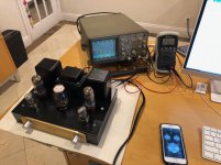
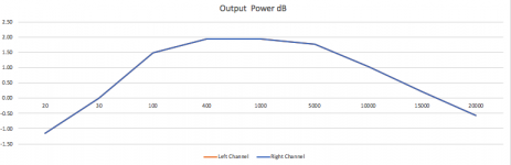
I did a frequency response test in my A9 tube amp with the original components that came in the kit. The idea is to see how the performance of my amp as it comes from china in the kit.
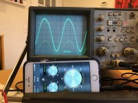
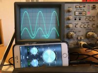
This is what I used for the test: Boyuu A9 tube amp (no modifications except the heater resistors to remove hum) 2x 8 ohms 100W resistors as loads. Hitachi V660 oscilloscope. Iphone with tone signal generator app (I know it’s a Pro tone generator but is the only one I had and, to be honest the wave form is pretty good. The problem is that is hard to set the exact frequency to “.00) Multimeter to measure dBm (I found out the meter does not respond well for low and high frequencies so I stopped using it)
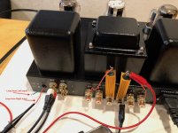
Setup: I put the 8 ohm resistors as load instead of the speakers so I wouldn’t drive my neighbor’s dog crazy with high frequencies �� I set the signal generator to the test frequency and set signal level to 1Vpp, I made the measurements and wrote the results in the Excel. I repeated this to all frequencies making sure to check the input signal level was always at 1 Vpp I used Channel A of the oscilloscope to measure the output signal and Channel B to measure the input signal. Note: In all pictures Ch B (input) is always the wave signal closest to the bottom of the screen) All measurements were made using the oscilloscope. I started using the multimeter to measure dBm but I gave up because it did not respond well for low and high frequencies, so the dBm had to be calculated from Vpp.
This is what I used for the test: Boyuu A9 tube amp (no modifications except the heater resistors to remove hum) 2x 8 ohms 100W resistors as loads. Hitachi V660 oscilloscope. Iphone with tone signal generator app (I know it’s a Pro tone generator but is the only one I had and, to be honest the wave form is pretty good. The problem is that is hard to set the exact frequency to “.00) Multimeter to measure dBm (I found out the meter does not respond well for low and high frequencies so I stopped using it)
Setup: I put the 8 ohm resistors as load instead of the speakers so I wouldn’t drive my neighbor’s dog crazy with high frequencies �� I set the signal generator to the test frequency and set signal level to 1Vpp, I made the measurements and wrote the results in the Excel. I repeated this to all frequencies making sure to check the input signal level was always at 1 Vpp I used Channel A of the oscilloscope to measure the output signal and Channel B to measure the input signal. Note: In all pictures Ch B (input) is always the wave signal closest to the bottom of the screen) All measurements were made using the oscilloscope. I started using the multimeter to measure dBm but I gave up because it did not respond well for low and high frequencies, so the dBm had to be calculated from Vpp.
Attachments
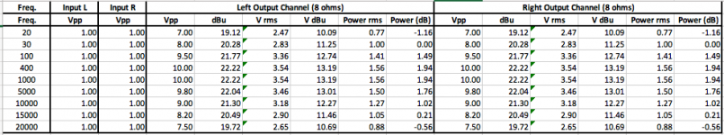
Frequency response Results:.
See the results in the Excel table.
I measured the Vpp of output and I used the formulas to calculate the Vrms, dBu, V dBu, Power rms and Power dBu. Feel free to double check my calculations.
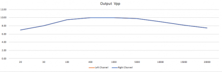
I plotted the results in a graphic using Excel chart function. Sorry the graphics are not log but I don’t know how to do a graphic in log it in Excel and I ran out of time.
As you can see the frequency response is bad below 400Hz and above 5Khz so I definitely will have to do some mods to get a good frequency response.
See the results in the Excel table.
I measured the Vpp of output and I used the formulas to calculate the Vrms, dBu, V dBu, Power rms and Power dBu. Feel free to double check my calculations.
I plotted the results in a graphic using Excel chart function. Sorry the graphics are not log but I don’t know how to do a graphic in log it in Excel and I ran out of time.
As you can see the frequency response is bad below 400Hz and above 5Khz so I definitely will have to do some mods to get a good frequency response.
Attachments
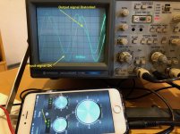
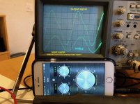
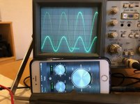
Here are the results for the Distortions test:
Please the pictures.
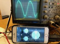
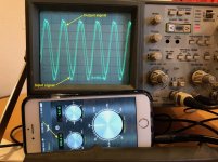
Note: you will see in some pictures I’ve overlapped the input and output signals so it’s easier to compare the two signals and detect distortions. And in some pictures I reduce the scale on the input to not overlap them. But independently on the scale showing on screen, the input signal was always 1Vpp.
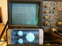
There is a distortion on the output signal for frequencies bellow 300Hz and it gets worse at 40Hz and bellow.
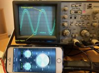
There are no distortions above 400Hz, even in high frequency like 20KHz the signal is clean.
I hope this information is useful to you guys and please send me suggestions of mods to improve the frequency response.
Cheers
Please the pictures.
Note: you will see in some pictures I’ve overlapped the input and output signals so it’s easier to compare the two signals and detect distortions. And in some pictures I reduce the scale on the input to not overlap them. But independently on the scale showing on screen, the input signal was always 1Vpp.
There is a distortion on the output signal for frequencies bellow 300Hz and it gets worse at 40Hz and bellow.
There are no distortions above 400Hz, even in high frequency like 20KHz the signal is clean.
I hope this information is useful to you guys and please send me suggestions of mods to improve the frequency response.
Cheers
Attachments
-
 IMG_4481.jpg140 KB · Views: 102
 -
 IMG_4485.jpg126.8 KB · Views: 89
 -
 IMG_300.jpg124.9 KB · Views: 64
 -
 IMG_200.jpg129.9 KB · Views: 76
 -
 IMG_100.jpg141.5 KB · Views: 81
 -
 IMG_80.jpg137.8 KB · Views: 71
 -
 IMG_1K.jpg145.9 KB · Views: 62
 -
 IMG_5Ks.jpg133.2 KB · Views: 65
 -
 IMG_10K.jpg142.3 KB · Views: 60
 -
 IMG_20Ks.jpg139.3 KB · Views: 75
Very interesting; thanks.Here are the results for the Distortions test:
Can your phone app generate square waves?
BTW, I'm assuming you checked/adjusted the compensation on your probes by hooking them to the 'Cal' on the front of the scope.
Very interesting; thanks.
Can your phone app generate square waves?
BTW, I'm assuming you checked/adjusted the compensation on your probes by hooking them to the 'Cal' on the front of the scope.
Hi VictoryGuy,
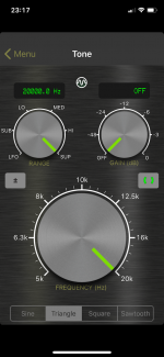
Yes, the app can do square, triangle and sawtooth waves. The app is called SIGNAL GENERATOR and is free on the App Store.
And yes, the problem were calibrated
Attachments
Hi,
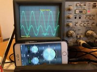
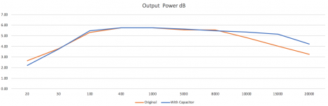
I did my first mod to the amp and added the capacitors as suggested in post#126.
I did not have a 470uF capacitor so I used a 330uF capacitor I had and I did see some improvements in high frequencies. I think the amp will have a much better high frequencies response with a 470UF capacitor when I get it.
The picture show a comparison between original and with a 330uF capacitor
@Gregas, I played a The Who vinyl album using an 1980's analog pre-amp connected to the A9 and it sounds OK but it definitely needs more high frequencies
Attachments
- Home
- Amplifiers
- Tubes / Valves
- Boyuu EL34 A9 Tube Amp