Navydiver said:
Is the '0' speaker terminal connected to the circuit ground? (not chassis). Yes via the coax wire that goes to the volume switch and then to the 6N9P octal sockets. The grounds ultimately go into the PCB common circuit ground.
Speaker terminal, not input jack.
Suggestions: Make a very short - 30s-60s video of the oscillation problem only, OR just attach a mp3 sound clip. You could do that here or start a new thread:
"Please help me troubleshoot my Chinese Boyuu amp" or something similar.
Showing clear pics of the inside of the amp so readers can see the connections to the front and back panels, and a shot of the back panel, will help.
Posting the schematic you used, again, will help - people don't want to search back through the thread if they are trying to help.
Try to make it easy for experts (not me!) to give you help.
Did you highlight each connection/component on the schematic as you soldered it in? Double-checking for wiring mistakes would be a good idea now. Some of the 'pictures' of amps have different tube socket orientations, so best to check the socket pinouts and connections against the schematic.
Look over your lead dress (routing of wiring) and solder joints.
For safety's sake, and for ease in measuring voltages, connect a wire from chassis ground to the PCB circuit ground as close to the 2nd filter cap as you can. You can attach it to a different place later to get the hum minimized, once you get the amp working.
Have a look at 'What about grounding output jacks' at
Grounding
He's talking about guitar amps which use a 1/4" phone jack for the speaker connection, so don't let the mention of 'sleeve' be confusing. Your '0 ohm' terminal has the same function.
Please use the reply box for responses - when you include your answer 'inside' my previous message, it is not available for me to comment.
You should be able to just use the go advanced mode at the bottom to embed comments. That is what I do - you can even select a different colour to differentiate your comments from mine
")
I have learned over the years, that:Please use the reply box for responses - when you include your answer 'inside' my previous message, it is not available for me to quote or comment.
The more work you demand of 'readers' who might be able to help, the fewer responses you will get.
This includes watching videos, searching for schematics, finding online resources and doing searches, etc...
Somehow you need to 'recruit' some experts who will be interested in guiding your troubleshooting.
Hi VictoriaGuy,
That section is pretty clear. It agrees with everything said so far unless there is some reason why that can't be done.
Ground lift switches area a common thing, but only used when needed. There is often an ad-hoc collection of gear in some recording sessions where the wiring has not been designed. Therefore you can easily create situations that favour ground loop hum. The switches save time and get the show rolling. In a permanent installation there is normally no need to lift the ground as there is time to sort out problems and fix them.
-Chris
Speaker terminal, not input jack.
Suggestions: Make a very short - 30s-60s video of the oscillation problem only, OR just attach a mp3 sound clip. You could do that here or start a new thread:
"Please help me troubleshoot my Chinese Boyuu amp" or something similar.
Showing clear pics of the inside of the amp so readers can see the connections to the front and back panels, and a shot of the back panel, will help.
Posting the schematic you used, again, will help - people don't want to search back through the thread if they are trying to help.
Try to make it easy for experts (not me!) to give you help.
Did you highlight each connection/component on the schematic as you soldered it in? Double-checking for wiring mistakes would be a good idea now. Some of the 'pictures' of amps have different tube socket orientations, so best to check the socket pinouts and connections against the schematic.
Look over your lead dress (routing of wiring) and solder joints.
For safety's sake, and for ease in measuring voltages, connect a wire from chassis ground to the PCB circuit ground as close to the 2nd filter cap as you can. You can attach it to a different place later to get the hum minimized, once you get the amp working.
Have a look at 'What about grounding output jacks' at
Grounding
He's talking about guitar amps which use a 1/4" phone jack for the speaker connection, so don't let the mention of 'sleeve' be confusing. Your '0 ohm' terminal has the same function.
Roger that, checking out. Thank you all.
For those who didn't look at the scan from Morgan Jones' "Building..." book, he states that the chassis ground and circuit ground should be connected together at the input jack.Hi VictoriaGuy,
That section is pretty clear. It agrees with everything said so far unless there is some reason why that can't be done.
BTW, this conversation (input jack vs filter caps for bonding to chassis ground) points out one of the difficulties of PCB-based construction when there aren't clear labels or instruction on the connections - like this Boyuu.
In a P2P build, it would be simple to solder a wire on to the same lug that connects the (-)ive lead of the filter cap. With a PCB like this one, the 'nearest' possible connection point may be unacceptable because of trace resistance, as Wavebourn explained.
Beginners really can benefit from clear directions. Here, Navydiver decided to forego the connection between chassis and circuit completely, since there was no consensus on exactly where to make the connection.
Roger that, checking out. Thank you all.
I hope you mean you are going to check out those things on the amp, not leaving.
Most folks here like problem-solving - you'll likely get more interest with a non-working amp than with a build that was successful right away!!
It’s hard to guess why local gurus send everyone to buy a bookThere's been a lot of talk about grounding and how best to do it. Can someone post some images of the amp so we can see exactly where on the circuit board. Or on the chassis?
To help newcomers is not included in their plans, you need to earn money by selling your own amplifiers.
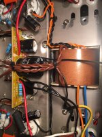
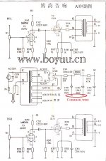
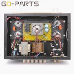
I have a ready amplifier to share the location of the common wire.
Attachments
Hi gregas,
Ground near the input jacks if possible.
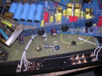
This is how I found one poor little Counterpoint SA-3.1. All the ground wires do connect to one spot near the input jacks, but the wiring is a disaster! Each ground wire was found to be close to the same length, so whoever did this is following some bizarre advice, or had their own little brainstorm. The later pictures show how I reran the grounds for both the input and output. Notice how the output ground connects to the ground point at the same location as the input grounds, but they are separate until they meet at the grounding post.
The last two pictures show "the ground" in a Marantz 2325. I pulled all the ground wires to one side to show the sheer number of ground wires that connect at this point. Impressive no? The 2325 is a quiet receiver, no hum at all. This ground is located close to the front panel on the right side of centre.
So here are two examples of proper grounding, one of which does not follow the general guidelines. But, it is still effective and done properly. Just as an aside, many receivers do not have one common ground point. They still manage to work okay, but they are not as quiet as the Marantz.
-Chris
Ground near the input jacks if possible.
This is how I found one poor little Counterpoint SA-3.1. All the ground wires do connect to one spot near the input jacks, but the wiring is a disaster! Each ground wire was found to be close to the same length, so whoever did this is following some bizarre advice, or had their own little brainstorm. The later pictures show how I reran the grounds for both the input and output. Notice how the output ground connects to the ground point at the same location as the input grounds, but they are separate until they meet at the grounding post.
The last two pictures show "the ground" in a Marantz 2325. I pulled all the ground wires to one side to show the sheer number of ground wires that connect at this point. Impressive no? The 2325 is a quiet receiver, no hum at all. This ground is located close to the front panel on the right side of centre.
So here are two examples of proper grounding, one of which does not follow the general guidelines. But, it is still effective and done properly. Just as an aside, many receivers do not have one common ground point. They still manage to work okay, but they are not as quiet as the Marantz.
-Chris
Attachments
Thanks for the reply guys. i see how you've done the grounding on those amps. How about speficially the A9. Does anyone care to share pics?
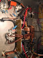
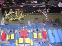
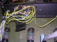
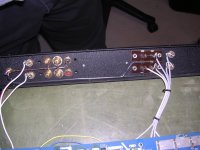
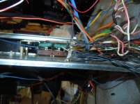
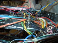
What are your thoughts on this way of doing the grounding. I've red circled what looks to be grounding points.
Speaker connection ground to chassis and circuit board a/c plug ground to chassis Ground connection from volume control to circuit board Grounded for el34 and 6n9pj heater circuit to the board.
Attachments
All
Back with a last ditch attempt at getting this A9 working prior to taking off on a ski vacation - thought I would be offline until the new year with work etc but found some play time this evening. Sorted out some of the issues but still not impressed with this crappy Chinese piece of poop (can you tell I am a bit frustrated?). Anyway, never give up, never surrender. Here is my latest update if anyone cares to watch (sorry but tired of typing - much easier to explain in a video):
Latest Video Sitrep with some questions here: YouTube
List of older Sitrep videos to track some history:
YouTube
YouTube
YouTube
YouTube
https://youtu.be/lNjLJeoXYFg
https://youtu.be/yWAerKgVXhA
https://youtu.be/MLhCwKIFzoE
navydiver,
Is it possible that one output transformer is wired out of phase?
If it is, the bass on the two speakers will cancel. Also, there will be no music in the middle between the speakers. Instead, it will appear to be only on the left and right sides, and can even appear to be outside of the spacing of the 2 speakers.
If the signals are out of phase, then just reverse the plus and common wires on just one (1) speaker. If that fixes the problem, you have to check the output transformer connections (or very unlikely one output transformer was made incorrectly).
Other possibilities: (versus schematic in post # 609; no global feedback, Ultra Linear mode) If the component values of C102 and R105 are wrong. If the values of C103 and R107 and R108 are wrong (too low of capacitance to bypass bass frequencies; too high of resistances will have less current in the EL34 and too high of a plate resistance to drive the output transformer inductance).
Too little inductance in the output transformer.
The same goes for the other channel: C202 R205; C203 R207 R208; Output transformer inductance.
Mis-wiring the output transformer primary: One incorrect wiring would have the B+ going to the Ultra Linear Tap, but would probably oscillate, if no oscillation it would certainly have less bass.
Another incorrect wiring with B+ on the transformer 'plate' lead, and tube plate lead on the transformer B+ lead would be closer to Triode mode, but would be better in overcoming the transformer inductance, and give more low bass, not less.
The third incorrect wiring would have the B+ on the transformer 'plate lead, and the tube plate lead on the ultra linear tap, and the screen on the transformer B+ lead. That would be hard on the EL34, and might possibly oscillate as well.
Actually there are 6 ways to connect the primary, but only one way gives the right result.
For either Ultra Linear operation, or for Triode wired operation, the total of the primary windings needs to be used: B+ to tube plate. That gives the most inductance load for the tube.
For Ultra Linear, you could use either 40% or 60%, depending on which ends of the primary B+ and EL34 Plate are connected; the Ultra Linear Screen tap always needs to be somewhere in the middle of the primary windings.
Last edited:
You've made some good progress - tracking down the wiring problem and getting rid of the oscillation is a major step.
Double checking the transformer wiring as 6A3 suggests is a good idea.
Even though people criticize the component quality and circuit choices on amps like the A9, I think that most of the major problems are due to wiring, so I try not to jump to thoughts of component upgrades, etc too quickly.
A systematic check of the DC voltages on the power and preamp tubes - plates, grids and cathodes is useful. Listing them here will give readers some ideas, perhaps. I usually do those measurements with the inputs shorted.
About hum- I haven't found in my builds that it makes much difference which chassis ground point I choose. The point in the circuit where that bond to the chassis is made (filter cap, input jack, or on a ground plane or ground bus) seems to make more difference.
Determining if it is 60Hz or 120 Hz hum - which you have done - is a good step. Even though you don't like typing (on your phone?), mentioning things like that 'in print' as well as in the video will help readers. Also, your videos probably won't last 'forever' on youtube, but the server here will keep uploaded text and pictures as long as the forum exists (with luck!). 'Video unavailable' is a common response when I'm reading older posts online.
One thing I'd double check is that the jacks are isolated from the chassis with the plastic washers.
Another would be cold solder joints, so a 'once-over' with a flux pen, solder and a hot iron is a standard step for me. You want a nice shiny solder connection at each point, and properly 'filled' connections on the PCB. If you over-do it with the solder (blob) , desoldering wick is very useful.
After that, lead dress is where I would focus my attention. Each improvement might make only a small change in hum level. One technique is to use a 'chopstick' (wood or plastic chopstick, or similar non-conductor) to move wires with the amp powered up and inputs shorted, speakers connected. Sometimes a problem causing hum can be found this way. Anything you can do to keep the AC (input power and heaters, HV AC from transformer) away from the low-level signal wiring will reduce hum. Good tight twisting and using the 'corners' of the chassis can help. If the two conductors are not the same gauge, it's difficult to get them twisted properly. Wrapping one conductor around the other (coiled around a straight conductor) helps, but an even twist is better.
Re-wiring and repair is always more difficult, so it can be frustrating unsoldering and moving components.
Have a good ski trip! When you come back to your project with 'fresh eyes' it will be easier!
When you get to the stage of dealing with the 'bass response' issue, using a 'test tones' recording - burnt to CD or from a computer or MP3 player - can help a lot.
If you look around online you can find some examples 'pre made' or you can generate tones with software. A $50-100 laptop with the right software can be handy, and less stressful than worrying about zapping your main computer/phone/tablet. Local online selling places in our area always have cheap machines available. Or grab a cheap audio generator from the local listings or a hamfest.
Hello Navydiver
I saw your youtube video's. I've got the same Boyuu kit since yesterday. With your movies and this forum some questions are right answered. I saw you have some wiring diagrams for the boards. Could I get them from you? Would you e-mail them to me? <removed email per request>
Thank you in advance! Greetings, Egon Smit (from The Netherlands)
Last edited by a moderator:
Incoming - 3 emails sent. Please feel free to contact me if you have any questions.
Cheers
Tim
Apparently it is somewhat bad form to append responses in red as I just read an admin PM from a while back in my inbox - Apologize for not seeing it sooner so admins please simply remove my latest response above if the colour coding thing is too garish.
Merry Christmas and Happy New Year all as I head off on extended holidays and thanks for all the feedback I have received thus far.
TMF
Have lots of that kind of stuff like Chesky records audiophile Test discs 1, 2 and 3 plus Stereophile Test CD (all lossless) plus some vinyl test stuff - also have a DIY tone generator I built and tested with my scope - not yet ready to use these items since even my old ears can simply tell it is simply far far off the mark
Will see how it goes when I resume in the new year
Cheers
Tim
My comments appended in red - comments and suggestions much appreciated.
Tim
Apparently it is somewhat bad form to append responses in red as I just read an admin PM from a while back in my inbox - Apologize for not seeing it sooner so admins please simply remove my latest response above if the colour coding thing is too garish.
Merry Christmas and Happy New Year all as I head off on extended holidays and thanks for all the feedback I have received thus far.
TMF
When you get to the stage of dealing with the 'bass response' issue, using a 'test tones' recording - burnt to CD or from a computer or MP3 player - can help a lot.
If you look around online you can find some examples 'pre made' or you can generate tones with software. A $50-100 laptop with the right software can be handy, and less stressful than worrying about zapping your main computer/phone/tablet. Local online selling places in our area always have cheap machines available. Or grab a cheap audio generator from the local listings or a hamfest.
Have lots of that kind of stuff like Chesky records audiophile Test discs 1, 2 and 3 plus Stereophile Test CD (all lossless) plus some vinyl test stuff - also have a DIY tone generator I built and tested with my scope - not yet ready to use these items since even my old ears can simply tell it is simply far far off the mark
Will see how it goes when I resume in the new year
Hey Guys,
Can anyone make suggestions what to measure in order to see if the amp is working as it should?
What tools (measuring devices) do you have?
- Home
- Amplifiers
- Tubes / Valves
- Boyuu EL34 A9 Tube Amp