Voltage test: With the transformer unloaded, the two 6.3V secondaries will have the same voltage, or nearly the same voltage.
Ohmmeter test: The DCR of the high current secondary will be lower than the 1 Amp secondary. You need a low range Ohm Ohmmeter to test this (and very good connections of the test leads to the secondary). If the readings are not stable, the DCR is lower than the connection resistance.
Under load: The EL34 filaments on the 1A secondary, and you have a hot secondary, and less than 6.3V (or less voltage than the high current secondary).
Last edited:
Yes - dial down the voltage to 15 volts AC or so, and connect that up to the primary. Then, even the HV secondary shouldn't have too 'exciting' a voltage on it. Still, be careful!I do have a Variac that I use for a DIY Acrylic Bending Machine I built. Thinking I could use that to keep the voltage levels way down???
I haven't exposed the leads on the transformers yet as I am waiting for a skookum wire stripper that I just ordered so I don't stress the wires trying to hand bomb it with hand strippers as per: Wire Stripper, EONLION Self-Adjusting Wire Stripping Tool/Cutting Pliers Tool with Wire Stripper/Crimper/Cutter, 8'': Amazon.ca: Tools & Home Improvement
I find that a simple stripper works pretty well for me.
If you are careful, a knife will also do the job.
Those 'self adjusting' strippers - at least the cheap ones I've had - have broken thin wires for me. They worked well on automotive/marine type wiring, though.
For testing voltages, it's often possible to just jam the meter probe points into the end of the wire without stripping the sheath. Once the wires are stripped, I almost always use test leads with alligator clips.
Tim:I was actually thinking about that (Paint is quite thick) - of course since there is no build diagram that comes with the unit I have no clue where the critical grounding points are to the chassis to do this are. Are you talking about the banana plug adapters for the 0, 4 and 8 ohm sockets (I don't really see any spur washers in the kit other than on the plugs)? Not sure also where on the chassis I would ground items as shown in the schematics - where I ground these items is not readily obvious to me????
The 'safety ground' - 'green' wire on the input AC connector needs to be connected to the chassis. Then, a short to the chassis will blow the house circuit breaker.
You want to make sure that any component that could get electrically 'hot' if there is a malfunction, is also connected to the chassis (and to that 'green wire). One example:You don't want a transformer case to be insulated from the chassis because it won't blow the breaker if there's a malfunction. So at least one of the bolts fastening the transformer to the chassis needs to have a good electrical connection to a) the chassis and b) the transformer.
I wouldn't depend on only the fasteners included with the kit. A few packages of spur and lock washers will come in handy.
John
It's important to keep thoughts about 'safety ground' separate from 'circuit ground'. The safety ground I'm talking about with the paint is just to make sure the breaker blows if something goes wrong - you don't want people to get a shock touching the transformer or a switch.Not sure also where on the chassis I would ground items as shown in the schematics - where I ground these items is not readily obvious to me????
Circuit ground is a whole different topic - plenty of reading to do on that!
")
You don't want to be 'grounding' different parts of the circuit to the chassis without a plan in place.
I have a question about the style of construction in this amp.
It's 'half-on and half-off' the PCB, and seems to have the components added and soldered 'from the top'.
I've built projects where the PCB is 'populated' with components and then connected with wires to the controls and tube sockets (many guitar amps use PCB or eyelet board like this). I've never built a project where there are components connecting the board to off-board tube sockets.
How do you solder the through-hole leads properly, working 'from the top'?
And how do you trim the leads after soldering?
Attachments

Thanks John
This is the meat of what I need to know so much appreciated. Will try hand bombing it - in fact I did just that building the dim bulb tester today and had no issues. The stripper will certainly come in handy on my boat which is what I really needed it for - especially in behind the helmet area and in the engine room. The lead legs seem to be quite long so will trim them down after testing with the variac and multimeter etc.
Pics of the dim bulb tester follow.
Great tips - many thanks.
Tim
Last edited:
I never mount tube sockets on PCBs. A first, they obstruct convection. And second, heat expands metals, so leads of sockets finally break solder joints. I guarantee my amps for 5 years, but hope that they will live forever. Modern components are better mounted on PCBs, so I may use PCBs standing vertically, for better convection path, connecting sockets by wires
you can take a photo
Many many thanks LongRoad - your provided schematics actually reflect the cap values I received - This is a very very good start. Have just begun proving the power transformer lines for continuity on the various windings (had to build my dim bulb tester first). This is a big help!
I also found this image on a Google search which reflects the exact PCB I have so will use it as somewhat of a rough guide to make sure what I do is making sense. I am first going to build as-is then will likely follow your guide for suggested mods once I have a firmer understanding of the build
.jpg")
Last edited:
Thank you agian John
1. Yeah won't exceed 15V to do the testing business. Makes sense even to a noob like me.
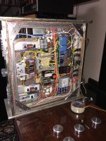
2. Just posted what I think is the best pic I have seen yet (from a noob POV of course) as it reflects my rig. I can't make out where the mains green wire is gorunded to the chassis for "safety ground". Hmmmm
3. Yeah, I thought the same as all the reading and Vids I have been watching seem to extol the virtues of point to point wiring vs PCB configurations. I plead plane ignorance on this one when I ordered it. I suppose it would be easy for better people than me to bin the PCB and go back to first principles????
4. Circuit grounding - I do understand the difference in basic terms but yes, more reading and getting smarts on this subject matter. I get the feeling I am many many miles from any kind of full comprehension on this topics
5. Doggy is bugging me for a comfort break - will have to get back to the rest after a good walk (maybe tomorrow as it is getting late and I just burned my last day off until next weekend

Thanks again
Tim
1. Yeah won't exceed 15V to do the testing business. Makes sense even to a noob like me.
2. Just posted what I think is the best pic I have seen yet (from a noob POV of course) as it reflects my rig. I can't make out where the mains green wire is gorunded to the chassis for "safety ground". Hmmmm
3. Yeah, I thought the same as all the reading and Vids I have been watching seem to extol the virtues of point to point wiring vs PCB configurations. I plead plane ignorance on this one when I ordered it. I suppose it would be easy for better people than me to bin the PCB and go back to first principles????
4. Circuit grounding - I do understand the difference in basic terms but yes, more reading and getting smarts on this subject matter. I get the feeling I am many many miles from any kind of full comprehension on this topics
5. Doggy is bugging me for a comfort break - will have to get back to the rest after a good walk (maybe tomorrow as it is getting late and I just burned my last day off until next weekend
Thanks again
Tim
Modern components are better mounted on PCBs,
Why are 'modern' components with leads not capable of being used in circuits the same way they have been for 80+ years? (i.e. connecting to tube sockets and solder lugs). Or do you mean surface mounted components (SMDs) are more 'modern' ? I agree that for 'rough handling' situations (vibration, lots of moving), laying the components with leads on a PCB is better, but home audio gear doesn't get very tough usage.
I recall taking apart some high-end (HP or Tek) equipment and it was full of PCBs with tube sockets. I also remember a tour of the SAGE (air defense) computer room - it was a tube computer designed in the early '50s - and that computer was built with plug in boards with tube sockets. They went through a lot of tubes. (By the 70s they were getting tubes from the USSR to keep it going!)
How do you manage grid stopper resistors? I don't think you would solder the resistor on the end of the wire....And, do you solder components across the tube sockets? That's a quite convenient thing when it works.so I may use PCBs standing vertically, for better convection path, connecting sockets by wires
I've learned a lot taking apart tube gear from the 50s and 60s.
After I posted that comment about 15 volts I realized I should have said 12 volts on the primary, so you could just multiply all your results by 10 to get the performance at 120 volts.1. Yeah won't exceed 15V to do the testing business. Makes sense even to a noob like me.
It looks to me like the yellow striped wire from the IEC AC inlet is taken to one of the choke mounting bolts- hopefully with a good crimped lug on the end, and spur washers, with the paint removed from the chassis.2. Just posted what I think is the best pic I have seen yet (from a noob POV of course) as it reflects my rig. I can't make out where the mains green wire is grounded to the chassis for "safety ground". Hmmmm
Nothing wrong with good PCB boards- they make a lot of sense for 'kits', and multiple builds. PCBs, perforated boards, eyelet boards, turret boards - lots of variations that can all be used to make good gear.3. Yeah, I thought the same as all the reading and Vids I have been watching seem to extol the virtues of point to point wiring vs PCB configurations. I plead plane ignorance on this one when I ordered it. I suppose it would be easy for better people than me to bin the PCB and go back to first principles????
The Tubelab boards from George are really nice - I still haven't built the amp, but the board is on my shelf here.....
Were tubes in that computers mounted horizontally, so boards did not obstruct convection path?
Why everything must be mounted on PCB? Not at all! Grid stoppers, interconnects, resistors between tube socket pins, and so on, can be mounted directly on the socket. But components designed to be mounted on PCB better be there. For example, electrolytic and film capacitors. And of course it is logical to mount some resistors, caps, etc.., between boards and sockets. I feel uneasy when I see heavy PCB mount caps glued to the chassis, or heavy resistors or boutique capacitors hanging on long thin wires... You say no vibrations and accelerations in home audio? What about shipment?
Here are examples attached, some of my prototypes. Not a visual art, but you can get the idea.
Attachments
Last edited:
Thanks for those comments and the pictures.
I think we basically agree on all points.
The Boyuu approach seems to encourage beginner builders to bolt the board to the chassis and solder the connections 'from the top', which I don't think is a good idea. However, it does help to secure the large caps to the PCB, which is good.
Add to the list: connections made 'in space' - not on a terminal or PCB.
I think we basically agree on all points.
The Boyuu approach seems to encourage beginner builders to bolt the board to the chassis and solder the connections 'from the top', which I don't think is a good idea. However, it does help to secure the large caps to the PCB, which is good.
Absolutely.But components designed to be mounted on PCB better be there.
For my projects, I'm able to find most of the capacitors with axial leads, so it's not a problem. Some 'can' caps - which in older gear were 'twist lock' into slots in the chassis - clamp to the chassis. For 'big' (uF) caps in SS circuits, there aren't many options, so a PCB is the best way - the only 'right way' with leads that are only a few mm long- to mount them.For example, electrolytic and film capacitors.
Me, too! More than uneasy for me - I hate to see that!I feel uneasy when I see heavy PCB mount caps glued to the chassis, or heavy resistors or boutique capacitors hanging on long thin wires...
Add to the list: connections made 'in space' - not on a terminal or PCB.
Good point! On the few occasions when I sell a project, the only 'shipment' is when the buyer carries the amp from my front door to their car. Still, I think we should all try to make our projects as 'rugged' as possible.You say no vibrations and accelerations in home audio? What about shipment?
I have to agree with Anatoliy. I find that modern components have shorter leads these days and often will not reach the terminals the original parts were soldered to. That's all.
-Chris
Chris-
Thanks.
I'd forgotten that. Once I read your comment, I remembered a couple of occasions where a replacement cap/resistor 'wouldn't reach' where the original had been.
For me, it's not a problem with building 'from scratch' - if the component leads won't reach - usually because of poor planning on my part - I bolt in another solder lug strip to attach the component, and then add a wire to 'the final destination'.
BTW, on my 'pet peeves' list is the fashion for right-angle bends to lift components in the air when it's not necessary. I like the leads to be short and direct. This is in P2P builds, where folks seem to think that electrons prefer to 'go around corners' and travel in parallel wires! Looks organized, but isn't always the best electronically.
If a resistor needs to be lifted above a PCB, I have some porcelain spacers from salvaged gear to do the job.
The basic construction principle that seems to often be ignored these days is that solder is for electrical - not mechanical - connections. It's something that was always right at the beginning of Heathkit manuals, and also in the 'Construction' chapter of the Radio Amateur Handbook.
Sorry for the long response!
(rant?)
Were tubes in that computers mounted horizontally, so boards did not obstruct convection path?
It was a long time ago, but my recollection is that the tubes were short (low profile) and the plug-in boards were mounted vertically.
The cabinets had LARGE forced air duct systems - ventilation and cooling were big problems. The entire 'building' was mounted on large springs and was underground in a hard rock 'mine', so ventilation air had to come from the surface above.
Very large diesel power plant was part of the system, and there were some interesting problems with the exhaust pipes (dozens of m. long, vertical)...a story for a different forum!
Here is a board for a stereo single ended amp that I designed yesterday. Waiting for them to be manufactured and shipped... One of advantages is, it can be used with any set of driver and output tubes, i.e. the board is universal.

One more examples, push-pull amp board, a single channel. Input triode, pentode, or cascode, does not matter, with Concertina phase splitter. Any tubes can be used. It was designed for my Hercules amp. Either LED or resistor+cap bias of input tube, also LED/LDR optical compressor can be soldered on the board.


If needed, I can add class A2 driver boards to any of them, either SE or PP one. All of them have 41 mm height, to fit under 1U chassis.

One more examples, push-pull amp board, a single channel. Input triode, pentode, or cascode, does not matter, with Concertina phase splitter. Any tubes can be used. It was designed for my Hercules amp. Either LED or resistor+cap bias of input tube, also LED/LDR optical compressor can be soldered on the board.
If needed, I can add class A2 driver boards to any of them, either SE or PP one. All of them have 41 mm height, to fit under 1U chassis.
After I posted that comment about 15 volts I realized I should have said 12 volts on the primary, so you could just multiply all your results by 10 to get the performance at 120 volts.
It looks to me like the yellow striped wire from the IEC AC inlet is taken to one of the choke mounting bolts- hopefully with a good crimped lug on the end, and spur washers, with the paint removed from the chassis.
Nothing wrong with good PCB boards- they make a lot of sense for 'kits', and multiple builds. PCBs, perforated boards, eyelet boards, turret boards - lots of variations that can all be used to make good gear.
The Tubelab boards from George are really nice - I still haven't built the amp, but the board is on my shelf here.....
John
Went with 12V as recommended for the X 10 factor which again makes sense to me (then I don't have to do ratios)
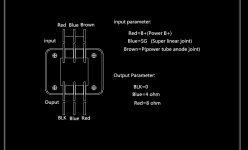
Here is what I get with an input voltage of 12.10 VAC (my cheap variac is quite touchy). From Brown to black (Center Tap - confirmed with resistance measurement first) it is 34.8 VAC on both sides (they agree perfectly). From brown to brown across the whole coil it is 69.5 VAC which is a little higher than the expected 640 VAC across both and 320 VAC for each center tap measurement (extrapolating to 10X). I would conclude from this that it is a 120V-ish transformer as it can't be 220 VAC with those numbers.
Is this actually a reasonable amount of tolerance or should I be getting another transformer? See photos (the 11.99 VAC shot was taken earlier and was difficult to repeat - the meter read 12.1 VAC when I took the other shots (close enough though I think.
Now to do the other smaller voltage measurements for the two 6.3 VAC coils and the 5 VAC coil...
Tim


Last edited:
Here is what I get with an input voltage of 12.10 VAC (my cheap variac is quite touchy). From Brown to black (Center Tap - confirmed with resistance measurement first) it is 34.8 VAC on both sides (they agree perfectly). From brown to brown across the whole coil it is 69.5 VAC which is a little higher than the expected 640 VAC across both and 320 VAC for each center tap measurement (extrapolating to 10X). I would conclude from this that it is a 120V-ish transformer as it can't be 220 VAC with those numbers.
Is this actually a reasonable amount of tolerance or should I be getting another transformer?
There are two 6.3 v windings - one rated for more current? Do the colour codes help with that?readings for the other coil pairings are 0.686 VAC for both 6.3 VAC coils and 0.543 VAC for the 5 VAC coil.
Tim
Those voltages look OK to me - once you get the amp built, if the B+ and filament/heater voltages are still a bit high, there are ways to correct the problem (bucking transformer, resistors, etc...) and you can deal with it then. I wouldn't worry about using that transformer, at all.
Sometimes using older transformers from the era of 110-115 AC supplies, I've run into the same thing.
What's your AC supply voltage at your place? 120 VAC? >120?
Nice compact boards.One more examples, push-pull amp board, a single channel. Input triode, pentode, or cascode, does not matter, with Concertina phase splitter. Any tubes can be used. It was designed for my Hercules amp. Either LED or resistor+cap bias of input tube, also LED/LDR optical compressor can be soldered on the board.
Not the schematic to send to a beginner, though! (Joking...)
It's important to keep thoughts about 'safety ground' separate from 'circuit ground'. The safety ground I'm talking about with the paint is just to make sure the breaker blows if something goes wrong - you don't want people to get a shock touching the transformer or a switch.
Circuit ground is a whole different topic - plenty of reading to do on that!
You don't want to be 'grounding' different parts of the circuit to the chassis without a plan in place.
John
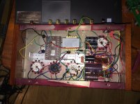
Ding, the light just went on with a big click! - just now looking at the schematic more closely as it relates to the main PCB in the real world wrt my project and I had a Tah-Dah moment! looking at the three large smoothing caps on the board I suddenly noted that all the negative terminals of the cap were following a large ground trace which I am now noting all the grounds in the various parts of the build lead to (with the exception of the two safety grounds in the schematic which are
1. coming off the 120V fused power cord socket to chassis and
2. the other being on the power transformer shell that also grounds to chassis). This was made far more clear in "LongRoad's" (thank you again LR) schematic as this is not at all detailed on the crap one I received from China. That one is also missing key parts of the circuit IMHO compared to LR's. I believe on the schematic he provided the safety grounds to chassis are marked with vertical hash marks underneath the horizontal ground line while circuit grounds (all leading to the PCB eventually) are simply marked as a horizontal line.
Big leap in understanding today (I think) but not getting cocky as I "know" I have much to learn and a long way to go still

There are two 6.3 v windings - one rated for more current? Do the colour codes help with that?
Those voltages look OK to me - once you get the amp built, if the B+ and filament/heater voltages are still a bit high, there are ways to correct the problem (bucking transformer, resistors, etc...) and you can deal with it then. I wouldn't worry about using that transformer, at all.
Sometimes using older transformers from the era of 110-115 AC supplies, I've run into the same thing.
What's your AC supply voltage at your place? 120 VAC? >120?
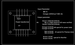
Thank you John. Yes on the 6.3 VAC - Markings are clear and match on my diagram. There is a size difference in wires as one pairing is for a max 2A load (Black wires) and the other is max 4A (orange wires). The two black thinner wires are for the 1A circuit feeding the heater on the 6N9P while the thicker orange wires are for the 3.5A circuit to feed the heaters on the EL34 tubes as best I can make out...
House was built in 1967 - 115.7 VAC at the socket - that may answer the delta
- Home
- Amplifiers
- Tubes / Valves
- Boyuu EL34 A9 Tube Amp